Pages

Translate

Friday, 17 July 2020

Complex Vector Addition :-

Complex Vector Addition :-

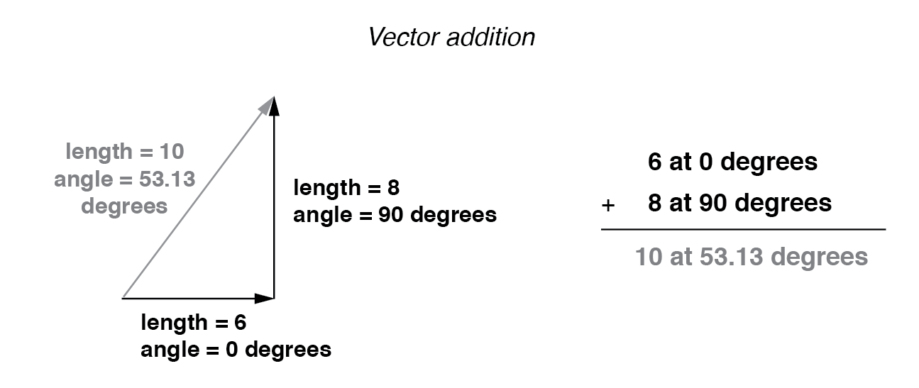
If vectors with uncommon angles are added, their magnitudes (lengths) add up quite differently than that of scalar magnitudes: (Figure below)


Vector magnitudes do not directly add for unequal angles.

Vector magnitudes do not directly add for unequal angles.


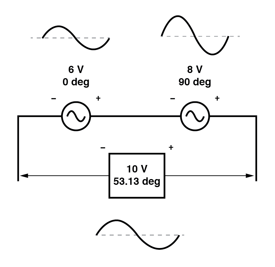
If two AC voltages—90° out of phase—are added together by being connected in series, their voltage magnitudes do not directly add or subtract as with scalar voltages in DC.

Instead, these voltage quantities are complex quantities, and just like the above vectors, which add up in a trigonometric fashion, a 6-volt source at 0° added to an 8-volt source at 90° results in 10 volts at a phase angle of 53.13°: (Figure below)


The 6V and 8V sources add to 10V with the help of trigonometry.

The 6V and 8V sources add to 10V with the help of trigonometry.


Compared to DC circuit analysis, this is very strange indeed. Note that it is possible to obtain voltmeter indications of 6 and 8 volts, respectively, across the two AC voltage sources, yet only read 10 volts for a total voltage!

There is no suitable DC analogy for what we’re seeing here with two AC voltages slightly out of phase. DC voltages can only directly aid or directly oppose, with nothing in between. With AC, two voltages can be aiding or opposing one another to any degree between fully-aiding and fully-opposing, inclusive.

Without the use of vector (complex number) notation to describe AC quantities, it would be very difficult to perform mathematical calculations for AC circuit analysis.

In the next section, we’ll learn how to represent vector quantities in symbolic rather than graphical form. Vector and triangle diagrams suffice to illustrate the general concept, but more precise methods of symbolism must be used if any serious calculations are to be performed on these quantities.


REVIEW :-

  •  DC voltages can only either directly aid or directly oppose each other when connected in series. AC voltages may aid or oppose to any degree depending on the phase shift between them.

Thursday, 16 July 2020

Simple Vector Addition :-

Simple Vector Addition :-

Remember that vectors are mathematical objects just like numbers on a number line: they can be added, subtracted, multiplied, and divided. Addition is perhaps the easiest vector operation to visualize, so we’ll begin with that. If vectors with common angles are added, their magnitudes (lengths) add up just like regular scalar quantities: (Figure below)


Vector magnitudes add like scalars for a common angle.


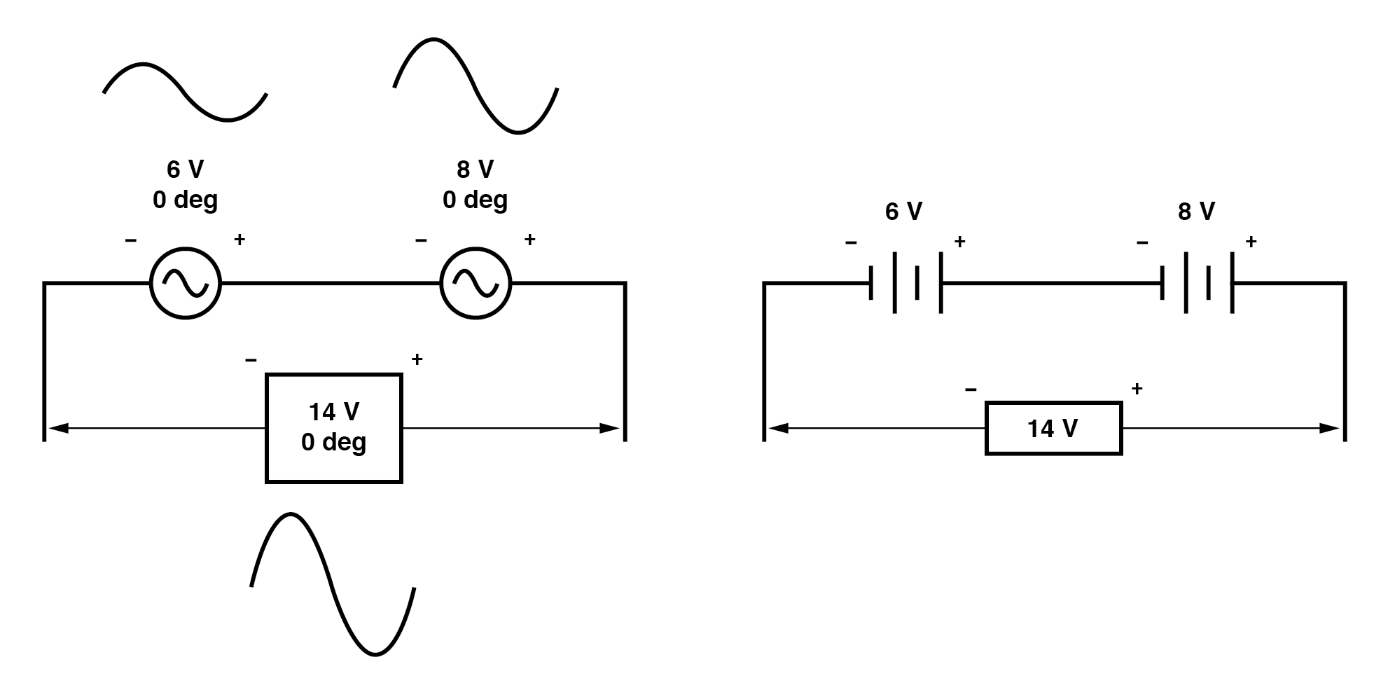
Similarly, if AC voltage sources with the same phase angle are connected together in series, their voltages add just as you might expect with DC batteries: (Figure below)


“In phase” AC voltages add like DC battery voltages.


Please note the (+) and (-) polarity marks next to the leads of the two AC sources. Even though we know AC doesn’t have “polarity” in the same sense that DC does, these marks are essential to know how to reference the given phase angles of the voltages. This will become more apparent in the next example.

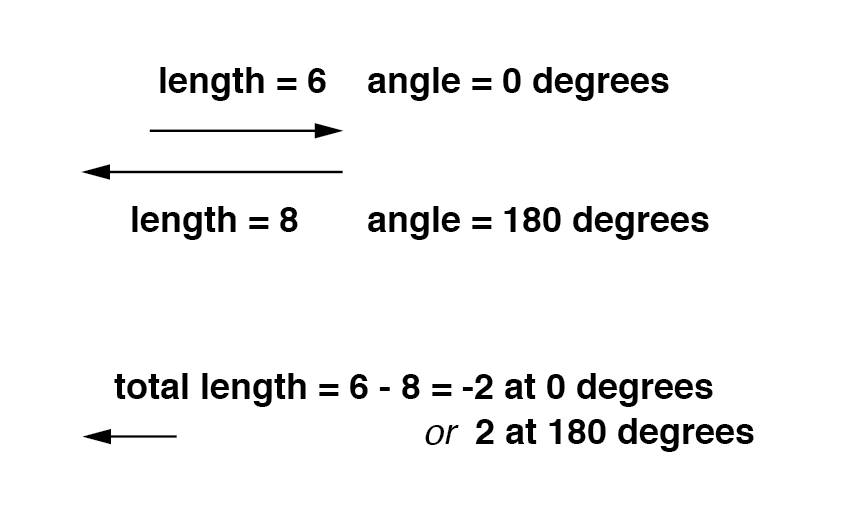
If vectors directly opposing each other (180° out of phase) are added together, their magnitudes (lengths) subtract just like positive and negative scalar quantities subtract when added: (Figure below)


Directly opposing vector magnitudes subtract.


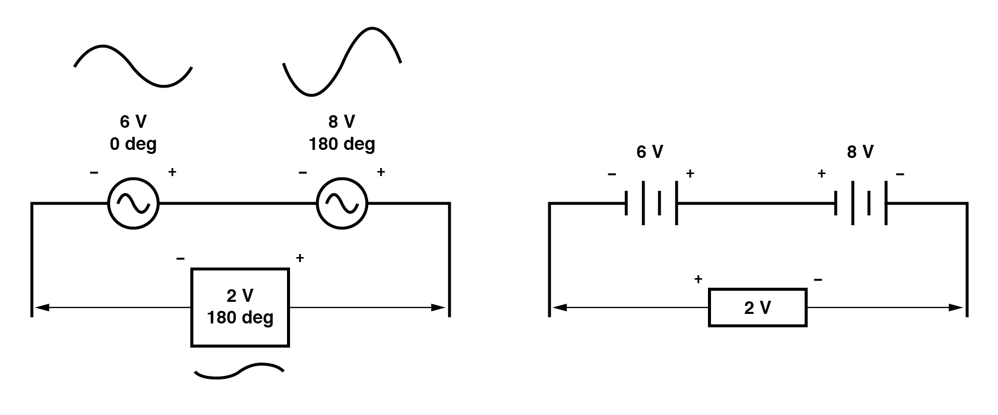
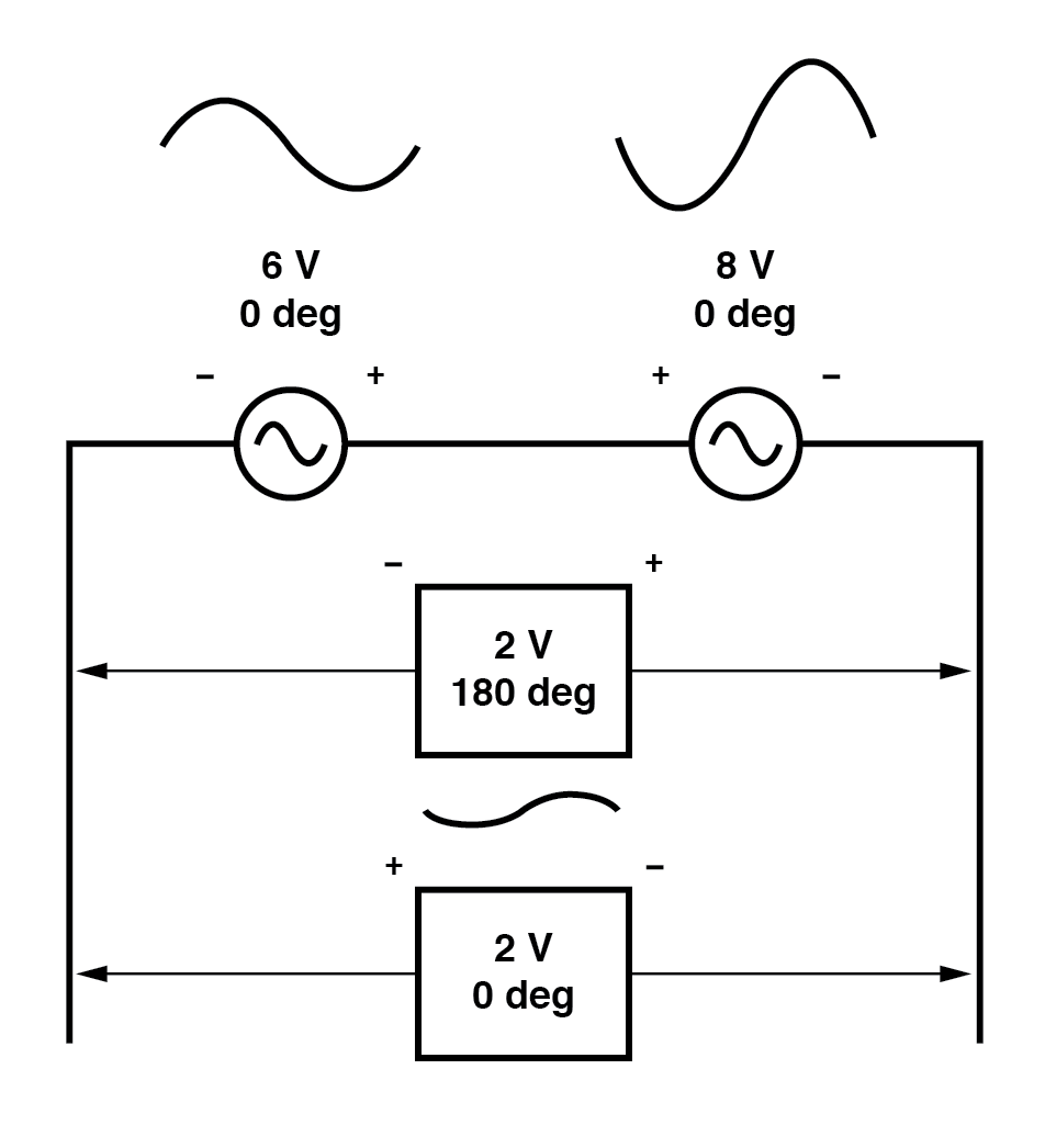
Similarly, if opposing AC voltage sources are connected in series, their voltages subtract as you might expect with DC batteries connected in an opposing fashion: (Figure below)


Opposing AC voltages subtract like opposing battery voltages.


Determining whether or not these voltage sources are opposing each other requires an examination of their polarity markings and their phase angles. Notice how the polarity markings in the above diagram seem to indicate additive voltages (from left to right, we see - and + on the 6 volt source, - and + on the 8 volt source).

Even though these polarity markings would normally indicate an additive effect in a DC circuit (the two voltages working together to produce a greater total voltage), in this AC circuit they’re actually pushing in opposite directions because one of those voltages has a phase angle of 0° and the other a phase angle of 180°.

The result, of course, is a total voltage of 2 volts.

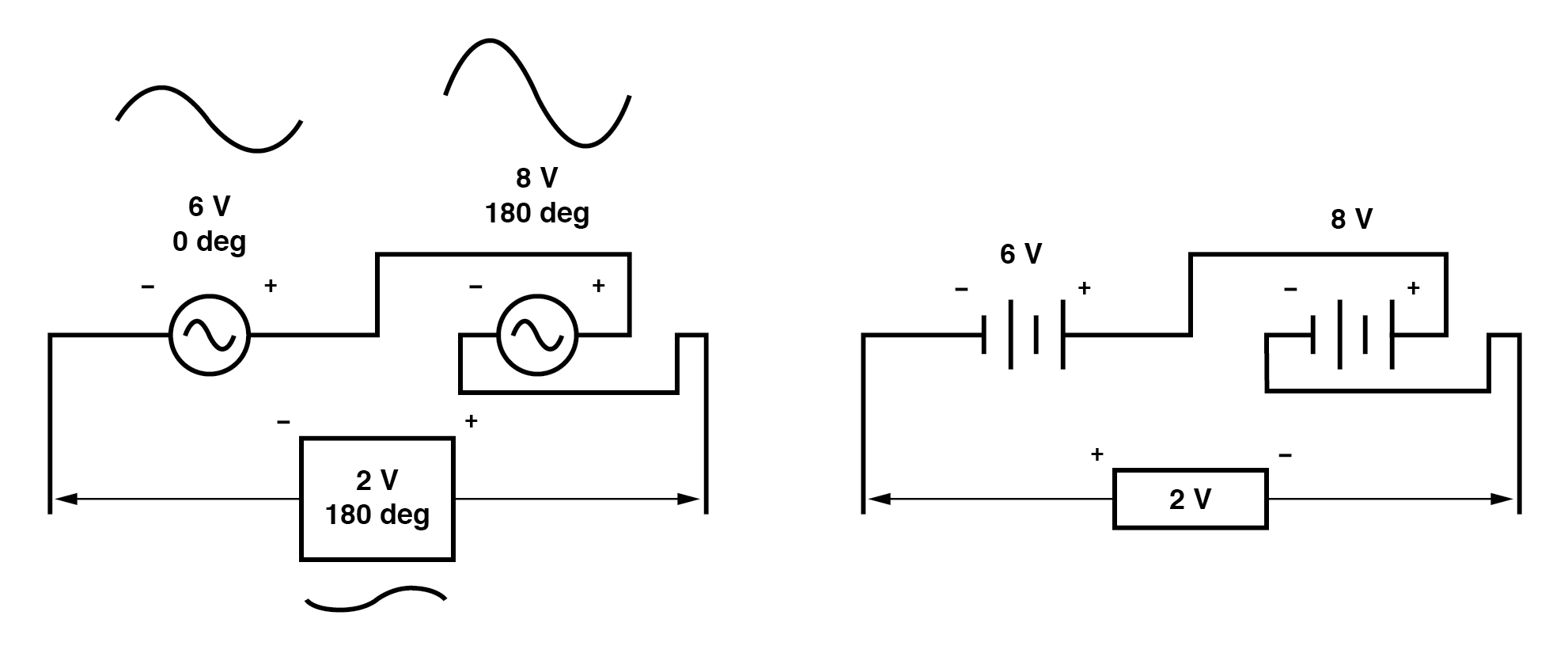
We could have just as well shown the opposing voltages subtracting in series like this: (Figure below)


Opposing voltages in spite of equal phase angles.


Note how the polarities appear to be opposed to each other now, due to the reversal of wire connections on the 8 volt source.

Since both sources are described as having equal phase angles (0°), they truly are opposed to one another, and the overall effect is the same as the former scenario with “additive” polarities and differing phase angles: a total voltage of only 2 volts. (Figure below)


Just as there are two ways to express the phase of the sources, there are two ways to express the resultant their sum.

Just as there are two ways to express the phase of the sources, there are two ways to express the resultant their sum.


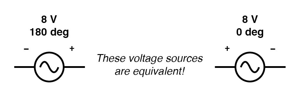
The resultant voltage can be expressed in two different ways: 2 volts at 180° with the (-) symbol on the left and the (+) symbol on the right, or 2 volts at 0° with the (+) symbol on the left and the (-) symbol on the right. A reversal of wires from an AC voltage source is the same as phase-shifting that source by 180°. (Figure below)

Example of equivalent voltage sources.

Example of equivalent voltage sources.

Wednesday, 15 July 2020

Vectors and AC Waveforms :-

Vectors and AC Waveforms :-

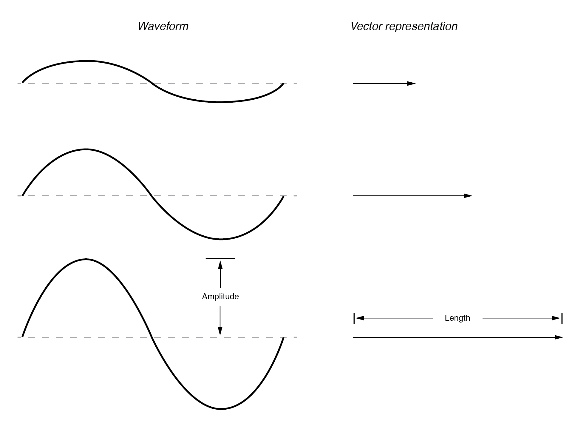
OK, so how exactly can we represent AC quantities of voltage or current in the form of a vector? The length of the vector represents the magnitude (or amplitude) of the waveform, like this: (Figure below)


Vector length represents AC voltage magnitude.


The greater the amplitude of the waveform, the greater the length of its corresponding vector. The angle of the vector, however, represents the phase shift in degrees between the waveform in question and another waveform acting as a “reference” in time.

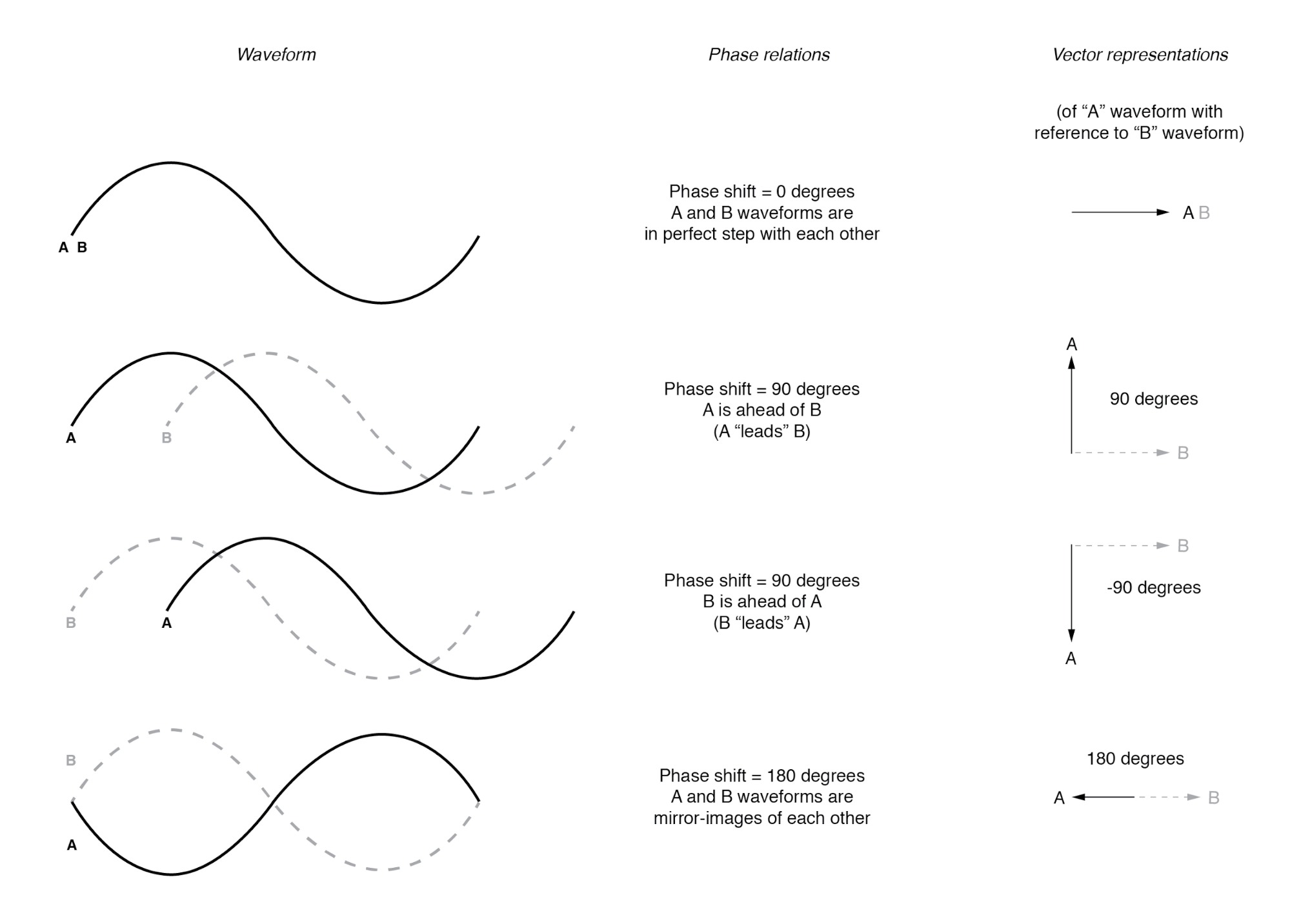
Usually, when the phase of a waveform in a circuit is expressed, it is referenced to the power supply voltage waveform (arbitrarily stated to be “at” 0°). Remember that phase is always a relative measurement between two waveforms rather than an absolute property. (Figure below)


Vector angle is the phase with respect to another waveform.


Phase shift between waves and vector phase angle


The greater the phase shift in degrees between two waveforms, the greater the angle difference between the corresponding vectors. Being a relative measurement, as the voltage, phase shift (vector angle) only has meaning in reference to some standard waveform.

Generally, this “reference” waveform is the main AC power supply voltage in the circuit. If there is more than one AC voltage source, then one of those sources is arbitrarily chosen to be the phase reference for all other measurements in the circuit.

This concept of a reference point is not unlike that of the “ground” point in a circuit for the benefit of the voltage reference.

With a clearly defined point in the circuit declared to be “ground,” it becomes possible to talk about voltage “on” or “at” single points in a circuit, being understood that those voltages (always relative between two points) are referenced to “ground.”

Correspondingly, with a clearly defined point of reference for phase, it becomes possible to speak of voltages and currents in an AC circuit having definite phase angles.

For example, if the current in an AC circuit is described as “24.3 milliamps at -64 degrees,” it means that the current waveform has an amplitude of 24.3 mA, and it lags 64° behind the reference waveform, usually assumed to be the main source voltage waveform.


REVIEW:-

  • When used to describe an AC quantity, the length of a vector represents the amplitude of the wave while the angle of a vector represents the phase angle of the wave relative to some other (reference) waveform.

Tuesday, 14 July 2020

Introduction to Complex Numbers :-

Complex Numbers :-

If I needed to describe the distance between two cities, I could provide an answer consisting of a single number in miles, kilometers, or some other unit of linear measurement.

However, if I were to describe how to travel from one city to another, I would have to provide more information than just the distance between those two cities; I would also have to provide information about the direction to travel, as well.

The kind of information that expresses a single dimension, such as linear distance, is called a scalar quantity in mathematics. Scalar numbers are the kind of numbers you’ve used in most all of your mathematical applications so far.

The voltage produced by a battery, for example, is a scalar quantity. So is the resistance of a piece of wire (ohms), or the current through it (amps).

However, when we begin to analyze AC circuits, we find that quantity of voltage, current, and even resistance (called impedance in AC) are not the familiar one-dimensional quantities we’re used to measuring in DC circuits.

Rather, these quantities, because they’re dynamic (alternating in direction and amplitude), possess other dimensions that must be taken into account. Frequency and phase shift are two of these dimensions that come into play.

Even with relatively simple AC circuits, where we’re only dealing with a single frequency, we still have the dimension of phase shift to contend with in addition to the amplitude.

In order to successfully analyze AC circuits, we need to work with mathematical objects and techniques capable of representing these multi-dimensional quantities.

Here is where we need to abandon scalar numbers for something better suited: complex numbers. Just like the example of giving directions from one city to another, AC quantities in a single-frequency circuit have both amplitude (analogy: distance) and phase shift (analogy: direction).

A complex number is a single mathematical quantity able to express these two dimensions of amplitude and phase shift at once.

Graphical Representation of Complex Numbers :-

Complex numbers are easier to grasp when they’re represented graphically. If I draw a line with a certain length (magnitude) and angle (direction), I have a graphic representation of a complex number which is commonly known in physics as a vector: (Figure below)
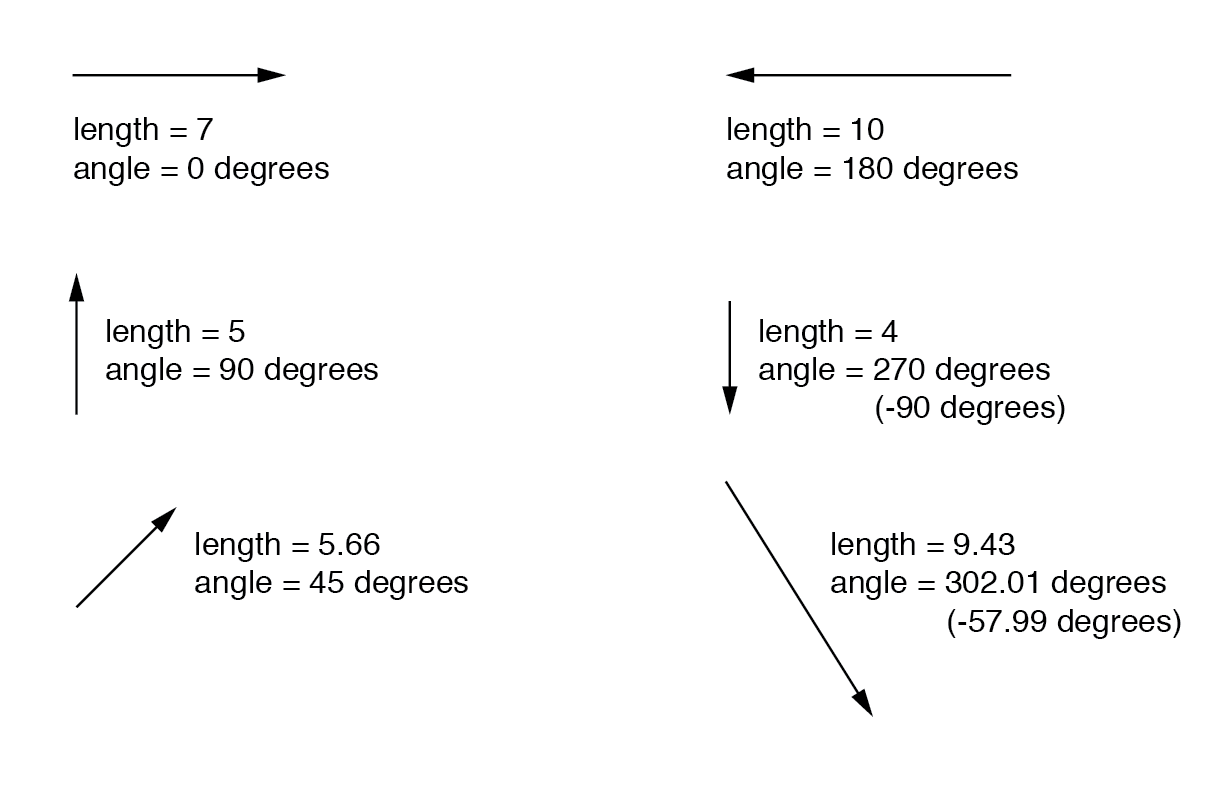
 

A vector has both magnitude and direction.


As distances and directions on a map, there must be some common frame of reference for angle figures to have any meaning. In this case, directly right is considered to be 0o, and angles are counted in a positive direction going counter-clockwise: (Figure below)
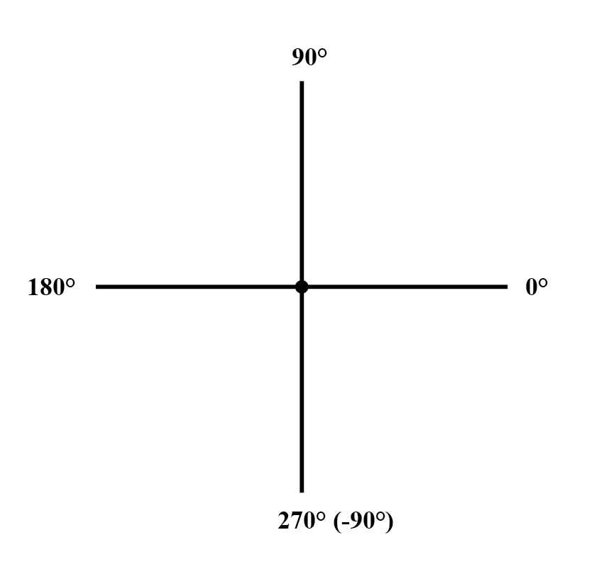
 

The vector compass


The idea of representing a number in graphical form is nothing new. We all learned this in grade school with the “number line:” (Figure below)

 

Number line.


We even learned how addition and subtraction works by seeing how lengths (magnitudes) stacked up to give a final answer: (Figure below)
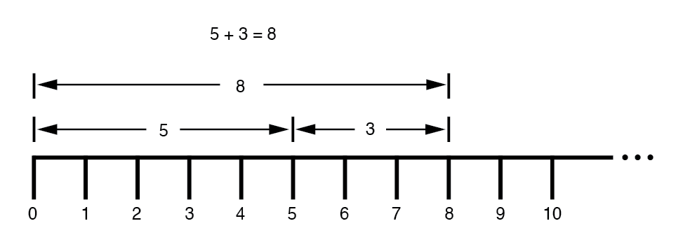
 

Addition on a “number line.


Later, we learned that there were ways to designate the values between the whole numbers marked on the line. These were fractional or decimal quantities: (Figure below)
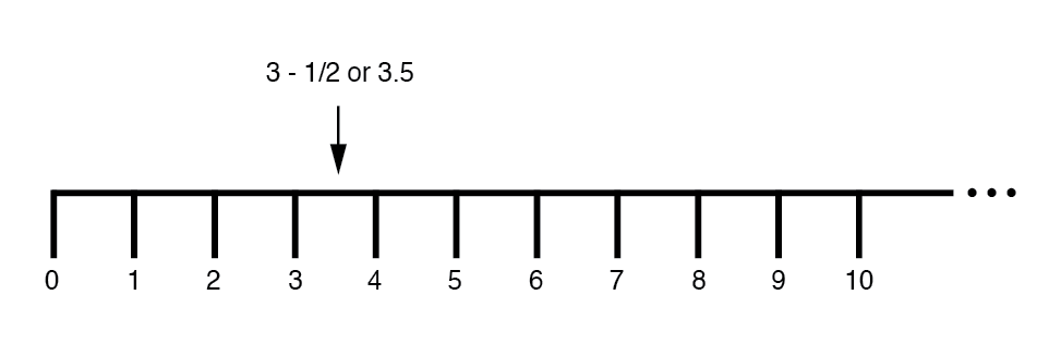
 

Number line” shows both positive and negative numbers.


These fields of numbers (whole, integer, rational, irrational, real, etc.) learned in grade school share a common trait: they’re all one-dimensional. The straightness of the number line illustrates this graphically.

You can move up or down the number line, but all “motion” along that line is restricted to a single axis (horizontal).

One-dimensional, scalar numbers are perfectly adequate for counting beads, representing weight, or measuring DC battery voltage, but they fall short of being able to represent something more complex like the distance and direction between two cities, or the amplitude and phase of an AC waveform.

To represent these kinds of quantities, we need multidimensional representations. In other words, we need a number line that can point in different directions, and that’s exactly what a vector is.


REVIEW :-

  • scalar number is the type of mathematical object that people are used to using in everyday life: a one-dimensional quantity like temperature, length, weight, etc.
  • complex number is a mathematical quantity representing two dimensions of magnitude and direction.
  • vector is a graphical representation of a complex number. It looks like an arrow, with a starting point, a tip, a definite length, and a definite direction. Sometimes the word phasor is used in electrical applications where the angle of the vector represents the phase shift between waveforms.
Monday, 13 July 2020

Principles of Radio ;-

Principles of Radio :-

One of the more fascinating applications of electricity is in the generation of invisible ripples of energy called radio waves. The limited scope of this lesson on alternating current does not permit full exploration of the concept, some of the basic principles will be covered.

With Oersted’s accidental discovery of electromagnetism, it was realized that electricity and magnetism were related to each other.

When an electric current was passed through a conductor, a magnetic field was generated perpendicular to the axis of flow. Likewise, if a conductor was exposed to a change in magnetic flux perpendicular to the conductor, a voltage was produced along the length of that conductor.

So far, scientists knew that electricity and magnetism always seemed to affect each other at right angles. However, a major discovery lay hidden just beneath this seemingly simple concept of related perpendicularity, and its unveiling was one of the pivotal moments in modern science.

Relationship of Electric and Magnetic Fields :-

This breakthrough in physics is hard to overstate. The man responsible for this conceptual revolution was the Scottish physicist James Clerk Maxwell (1831-1879), who “unified” the study of electricity and magnetism in four relatively tidy equations.

In essence, what he discovered was that electric and magnetic fields were intrinsically related to one another, with or without the presence of a conductive path for current to flow. Stated more formally, Maxwell’s discovery was this:

A changing electric field produces a perpendicular magnetic field, and

A changing magnetic field produces a perpendicular electric field.

All of this can take place in open space, the alternating electric and magnetic fields supporting each other as they travel through space at the speed of light. This dynamic structure of electric and magnetic fields propagating through space is better known as an electromagnetic wave.

There are many kinds of natural radiative energy composed of electromagnetic waves. Even light is electromagnetic in nature. So are X-rays and “gamma” ray radiation.

The only difference between these kinds of electromagnetic radiation is the frequency of their oscillation (alternation of the electric and magnetic fields back and forth in polarity). By using a source of AC voltage and a special device called an antenna, we can create electromagnetic waves (of a much lower frequency than that of light) with ease.

Types of Antenna :-

An antenna is nothing more than a device built to produce a dispersing electric or magnetic field. Two fundamental types of antennae are the dipole and the loop: Figure below

Dipole and loop antennas

Dipole and loop antennas.

While the dipole looks like nothing more than an open circuit, and the loop a short circuit, these pieces of wire are effective radiators of electromagnetic fields when connected to AC sources of the proper frequency. The two open wires of the dipole act as a sort of capacitor (two conductors separated by a dielectric), with the electric field open to dispersal instead of being concentrated between two closely-spaced plates.

The closed wire path of the loop antenna acts like an inductor with a large air core, again providing ample opportunity for the field to disperse away from the antenna instead of being concentrated and contained as in a normal inductor.

As the powered dipole radiates its changing electric field into space, a changing magnetic field is produced at right angles, thus sustaining the electric field further into space, and so on as the wave propagates at the speed of light.

As the powered loop antenna radiates its changing magnetic field into space, a changing electric field is produced at right angles, with the same end-result of a continuous electromagnetic wave sent away from the antenna. Either antenna achieves the same basic task: the controlled production of an electromagnetic field.

Functions of an Antenna :-

When attached to a source of high-frequency AC power, an antenna acts as a transmitting device, converting AC voltage and current into electromagnetic wave energy. Antennas also have the ability to intercept electromagnetic waves and convert their energy into AC voltage and current. In this mode, an antenna acts as a receiving device: Figure below

Basic radio transmitter and receiver

Basic radio transmitter and receiver.


While there is much more that may be said about antenna technology, this brief introduction is enough to give you the general idea of what’s going on (and perhaps enough information to provoke a few experiments).


REVIEW :-

  • James Maxwell discovered that changing electric fields produce perpendicular magnetic fields, and vice versa, even in empty space.
  • A twin set of electric and magnetic fields, oscillating at right angles to each other and traveling at the speed of light, constitutes an electromagnetic wave.
  • An antenna is a device made of wire, designed to radiate a changing electric field or changing magnetic field when powered by a high-frequency AC source, or intercept an electromagnetic field and convert it to an AC voltage or current.
  • The dipole antenna consists of two pieces of wire (not touching), primarily generating an electric field when energized, and secondarily producing a magnetic field in space.
  • The loop antenna consists of a loop of wire, primarily generating a magnetic field when energized, and secondarily producing an electric field in space.

Sunday, 12 July 2020

AC Phase :-

AC Phase :-

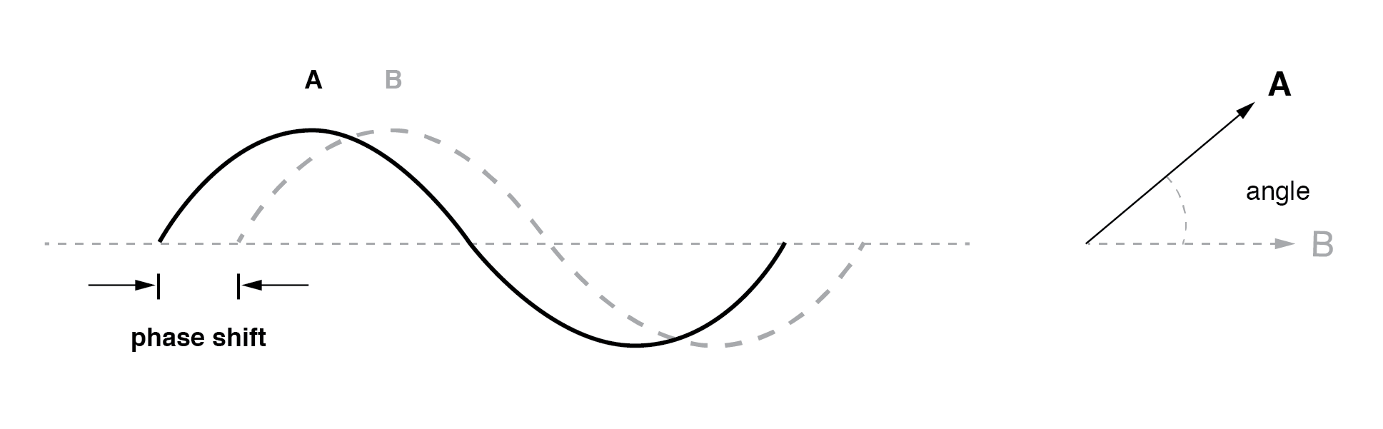
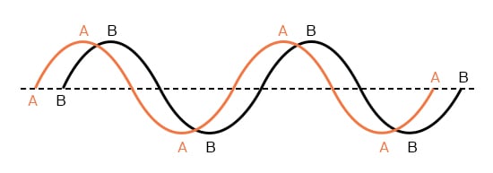
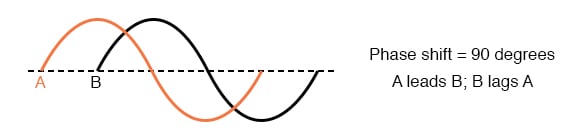
Things start to get complicated when we need to relate two or more AC voltages or currents that are out of step with each other. By “out of step,” I mean that the two waveforms are not synchronized: that their peaks and zero points do not match up at the same points in time. The graph in figure below illustrates an example of this.

Out of phase waveforms

Out of phase waveforms.


The two waves shown above (A versus B) are of the same amplitude and frequency, but they are out of step with each other. In technical terms, this is called a phase shift. Earlier we saw how we could plot a “sine wave” by calculating the trigonometric sine function for angles ranging from 0 to 360 degrees, a full circle.

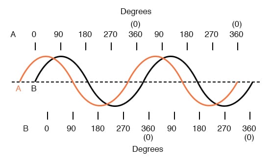
The starting point of a sine wave was zero amplitude at zero degrees, progressing to full positive amplitude at 90 degrees, zero at 180 degrees, full negative at 270 degrees, and back to the starting point of zero at 360 degrees. We can use this angle scale along the horizontal axis of our waveform plot to express how far out of step one wave is with another: Figure below

Wave A leads wave B by 45°

Wave A leads wave B by 45°


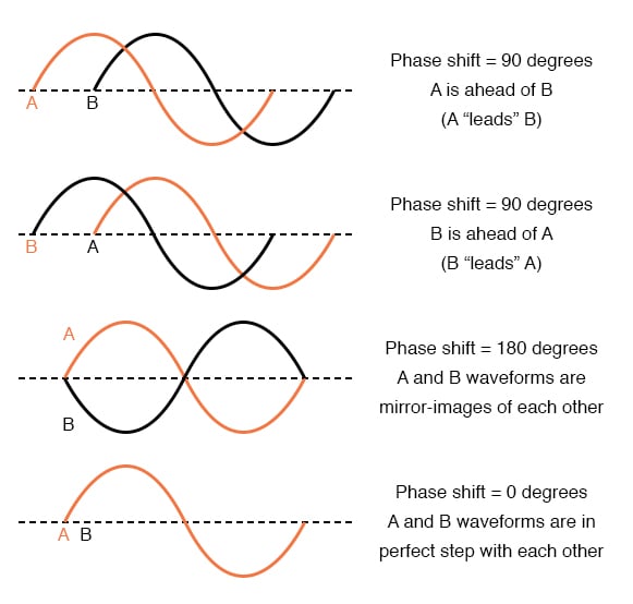
The shift between these two waveforms is about 45 degrees, the “A” wave being ahead of the “B” wave. A sampling of different phase shifts is given in the following graphs to better illustrate this concept: Figure below

Examples of phase shifts.

Examples of phase shifts.

Because the waveforms in the above examples are at the same frequency, they will be out of step by the same angular amount at every point in time. For this reason, we can express phase shift for two or more waveforms of the same frequency as a constant quantity for the entire wave, and not just an expression of shift between any two particular points along the waves. That is, it is safe to say something like, “voltage ‘A’ is 45 degrees out of phase with voltage ‘B’.” Whichever waveform is ahead in its evolution is said to be leading and the one behind is said to be lagging.

Phase shift, like voltage, is always a measurement relative between two things. There’s really no such thing as a waveform with an absolute phase measurement because there’s no known universal reference for phase. Typically in the analysis of AC circuits, the voltage waveform of the power supply is used as a reference for phase, that voltage stated as “xxx volts at 0 degrees.” Any other AC voltage or current in that circuit will have its phase shift expressed in terms relative to that source voltage.

This is what makes AC circuit calculations more complicated than DC. When applying Ohm’s Law and Kirchhoff’s Laws, quantities of AC voltage and current must reflect phase shift as well as amplitude. Mathematical operations of addition, subtraction, multiplication, and division must operate on these quantities of phase shift as well as amplitude. Fortunately, there is a mathematical system of quantities called complex numbers ideally suited for this task of representing amplitude and phase.

Because the subject of complex numbers is so essential to the understanding of AC circuits, the next chapter will be devoted to that subject alone.


REVIEW :-

  • Phase shift is where two or more waveforms are out of step with each other.
  • The amount of phase shift between two waves can be expressed in terms of degrees, as defined by the degree units on the horizontal axis of the waveform graph used in plotting the trigonometric sine function.
  • leading waveform is defined as one waveform that is ahead of another in its evolution. A lagging waveform is one that is behind another. Example:

lagging waveform

  • Calculations for AC circuit analysis must take into consideration both amplitude and phase shift of voltage and current waveforms to be completely accurate. This requires the use of a mathematical system called complex numbers.

Saturday, 11 July 2020

Simple AC Circuit Calculations :-

Simple AC Circuit Calculations :-

Over the course of the next few chapters, you will learn that AC circuit measurements and calculations can get very complicated due to the complex nature of alternating current in circuits with inductance and capacitance.

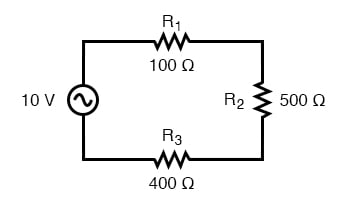
However, with simple circuits (figure below) involving nothing more than an AC power source and resistance, the same laws and rules of DC apply simply and directly.

AC circuit calculations for resistive circuits are the same as for DC.

AC circuit calculations for resistive circuits are the same as for DC.


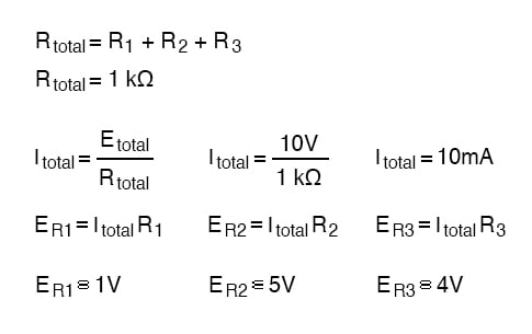
ac circuit equation


Series resistances still add, parallel resistances still diminish, and the Laws of Kirchhoff and Ohm still hold true. Actually, as we will discover later on, these rules and laws always hold true, it’s just that we have to express the quantities of voltage, current, and opposition to current in more advanced mathematical forms.

With purely resistive circuits, however, these complexities of AC are of no practical consequence, and so we can treat the numbers as though we were dealing with simple DC quantities.

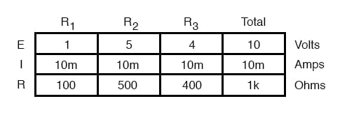
Because all these mathematical relationships still hold true, we can make use of our familiar “table” method of organizing circuit values just as with DC:

circuit values table

One major caveat needs to be given here: all measurements of AC voltage and current must be expressed in the same terms (peak, peak-to-peak, average, or RMS). If the source voltage is given in peak AC volts, then all currents and voltages subsequently calculated are cast in terms of peak units.

If the source voltage is given in AC RMS volts, then all calculated currents and voltages are cast in AC RMS units as well. This holds true for any calculation based on Ohm’s Laws, Kirchhoff’s Laws, etc. Unless otherwise stated, all values of voltage and current in AC circuits are generally assumed to be RMS rather than peak, average, or peak-to-peak.

In some areas of electronics, peak measurements are assumed, but in most applications (especially industrial electronics) the assumption is RMS.


REVIEW :-

  • All the old rules and laws of DC (Kirchhoff’s Voltage and Current Laws, Ohm’s Law) still hold true for AC. However, with more complex circuits, we may need to represent the AC quantities in more complex form. More on this later, I promise!
  • The “table” method of organizing circuit values is still a valid analysis tool for AC circuits.

Simple Parallel (Tank Circuit) Resonance :-

  Resonance in a Tank Circuit :- A condition of resonance will be experienced in a tank circuit when the reactance of the capacitor and  ind...