Pages

Translate

Showing posts with label Basic Concepts Of Electrical Engineering. Show all posts

Sunday, 12 July 2020

AC Phase :-

AC Phase :-

Things start to get complicated when we need to relate two or more AC voltages or currents that are out of step with each other. By “out of step,” I mean that the two waveforms are not synchronized: that their peaks and zero points do not match up at the same points in time. The graph in figure below illustrates an example of this.
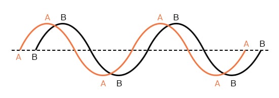
Out of phase waveforms

Out of phase waveforms.


The two waves shown above (A versus B) are of the same amplitude and frequency, but they are out of step with each other. In technical terms, this is called a phase shift. Earlier we saw how we could plot a “sine wave” by calculating the trigonometric sine function for angles ranging from 0 to 360 degrees, a full circle.

The starting point of a sine wave was zero amplitude at zero degrees, progressing to full positive amplitude at 90 degrees, zero at 180 degrees, full negative at 270 degrees, and back to the starting point of zero at 360 degrees. We can use this angle scale along the horizontal axis of our waveform plot to express how far out of step one wave is with another: Figure below
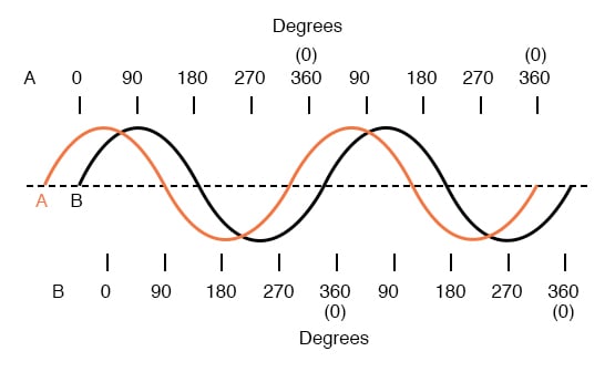
Wave A leads wave B by 45°

Wave A leads wave B by 45°


The shift between these two waveforms is about 45 degrees, the “A” wave being ahead of the “B” wave. A sampling of different phase shifts is given in the following graphs to better illustrate this concept: Figure below
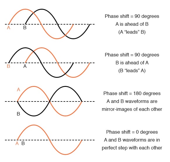
Examples of phase shifts.

Examples of phase shifts.

Because the waveforms in the above examples are at the same frequency, they will be out of step by the same angular amount at every point in time. For this reason, we can express phase shift for two or more waveforms of the same frequency as a constant quantity for the entire wave, and not just an expression of shift between any two particular points along the waves. That is, it is safe to say something like, “voltage ‘A’ is 45 degrees out of phase with voltage ‘B’.” Whichever waveform is ahead in its evolution is said to be leading and the one behind is said to be lagging.

Phase shift, like voltage, is always a measurement relative between two things. There’s really no such thing as a waveform with an absolute phase measurement because there’s no known universal reference for phase. Typically in the analysis of AC circuits, the voltage waveform of the power supply is used as a reference for phase, that voltage stated as “xxx volts at 0 degrees.” Any other AC voltage or current in that circuit will have its phase shift expressed in terms relative to that source voltage.

This is what makes AC circuit calculations more complicated than DC. When applying Ohm’s Law and Kirchhoff’s Laws, quantities of AC voltage and current must reflect phase shift as well as amplitude. Mathematical operations of addition, subtraction, multiplication, and division must operate on these quantities of phase shift as well as amplitude. Fortunately, there is a mathematical system of quantities called complex numbers ideally suited for this task of representing amplitude and phase.

Because the subject of complex numbers is so essential to the understanding of AC circuits, the next chapter will be devoted to that subject alone.


REVIEW :-

  • Phase shift is where two or more waveforms are out of step with each other.
  • The amount of phase shift between two waves can be expressed in terms of degrees, as defined by the degree units on the horizontal axis of the waveform graph used in plotting the trigonometric sine function.
  • A leading waveform is defined as one waveform that is ahead of another in its evolution. A lagging waveform is one that is behind another. Example:
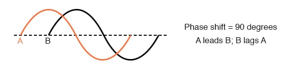
lagging waveform

  • Calculations for AC circuit analysis must take into consideration both amplitude and phase shift of voltage and current waveforms to be completely accurate. This requires the use of a mathematical system called complex numbers.

Saturday, 11 July 2020

Simple AC Circuit Calculations :-

Simple AC Circuit Calculations :-

Over the course of the next few chapters, you will learn that AC circuit measurements and calculations can get very complicated due to the complex nature of alternating current in circuits with inductance and capacitance.

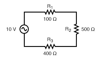
However, with simple circuits (figure below) involving nothing more than an AC power source and resistance, the same laws and rules of DC apply simply and directly.

AC circuit calculations for resistive circuits are the same as for DC.

AC circuit calculations for resistive circuits are the same as for DC.


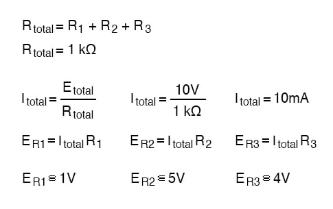
ac circuit equation


Series resistances still add, parallel resistances still diminish, and the Laws of Kirchhoff and Ohm still hold true. Actually, as we will discover later on, these rules and laws always hold true, it’s just that we have to express the quantities of voltage, current, and opposition to current in more advanced mathematical forms.

With purely resistive circuits, however, these complexities of AC are of no practical consequence, and so we can treat the numbers as though we were dealing with simple DC quantities.

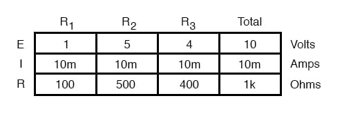
Because all these mathematical relationships still hold true, we can make use of our familiar “table” method of organizing circuit values just as with DC:

circuit values table

One major caveat needs to be given here: all measurements of AC voltage and current must be expressed in the same terms (peak, peak-to-peak, average, or RMS). If the source voltage is given in peak AC volts, then all currents and voltages subsequently calculated are cast in terms of peak units.

If the source voltage is given in AC RMS volts, then all calculated currents and voltages are cast in AC RMS units as well. This holds true for any calculation based on Ohm’s Laws, Kirchhoff’s Laws, etc. Unless otherwise stated, all values of voltage and current in AC circuits are generally assumed to be RMS rather than peak, average, or peak-to-peak.

In some areas of electronics, peak measurements are assumed, but in most applications (especially industrial electronics) the assumption is RMS.


REVIEW :-

  • All the old rules and laws of DC (Kirchhoff’s Voltage and Current Laws, Ohm’s Law) still hold true for AC. However, with more complex circuits, we may need to represent the AC quantities in more complex form. More on this later, I promise!
  • The “table” method of organizing circuit values is still a valid analysis tool for AC circuits.

Friday, 12 June 2020

Electric Potential :-


Electric Potential

When a body is charged, work is done in charging it. This work done is stored in the body
in the form of potential energy. The charged body has the capacity to do work by moving other
charges either by attraction or repulsion. The ability of the charged body to do work is called electric
potential. The capacity of a charged body to do work is called its electric potential.
The greater the capacity of a charged body to do work, the greater is its electric potential.
Obviously, the work done to charge a body to 1 coulomb will be a measure of its electric potential
i.e. Electric potential, V =Work done/Charge = W/Q
The work done is measured in joules and charge in coulombs. Therefore, the unit of electric
potential will be joules/coulomb or volt. If W = 1 joule, Q = 1 coulomb, then V = 1/1 = 1 volt.
Hence a body is said to have an electric potential of 1 volt if 1 joule of work is done to
give it a charge of 1 coulomb. Thus, when we say that a body has an electric potential of 5 volts, it means that 5 joules of work has been done to charge the body to 1 coulomb. In other words, every coulomb of charge possesses an energy of 5 joules. The greater the joules/coulomb on a charged body, the greater is its electric potential.


Potential Difference

The difference in the potentials of two charged bodies is called potential difference.
If two bodies have different electric potentials, a potential difference exists between the bodies. Consider two bodies A and B having potentials of 5 volts and 3 volts respectively  Each coulomb of charge on body A has an energy of 5 joules while each coulomb of charge on body B has an energy of 3 joules. Clearly, body A is at higher potential than the body B.
If the two bodies are joined through a conductor [See Fig. 1.6 (ii)], then electrons will *flow
from body B to body A. When the two bodies attain the same potential, the flow of current stops. Therefore, we arrive at a very important conclusion that current will flow in a circuit if potential difference exists. No potential difference, no current flow. It may be noted that potential difference is sometimes called voltage.
Unit. Since the unit of electric potential is volt, one can expect that unit of potential difference
will also be volt. It is defined as under :
The potential difference between two points is 1 volt if one joule of work is **done or released in transferring 1 coulomb of charge from one point to the other.

Thursday, 11 June 2020

Electric Current :-


Electric Current

The directed flow of free electrons (or charge) is called electric current. The flow of electric current can be beautifully explained by referring to. The copper strip has a large number of free electrons. When electric pressure or voltage is applied, then free electrons, being negatively charged, will start moving towards the positive terminal around the circuit as . This directed flow of electrons is called electric current. The reader may note the following points :
(i) Current is flow of electrons and electrons are the constituents of matter. Therefore, electric current is matter (i.e. free electrons) in motion.
(ii) The actual direction of current (i.e. flow of electrons) is from negative terminal to the positive terminal through that part of the circuit external to the cell. However, prior to Electron theory, it was assumed that current flowed from positive terminal to the negative terminal of the cell 
via the circuit. This convention is so firmly established that it is still in use. This assumed direction
of current is now called conventional current.

Unit of Current.

The strength of electric current I is the rate of flow of electrons i.e. charge flowing per second.
 Current, I = Q/t
The charge Q is measured in coulombs and time t in seconds. Therefore, the unit of electric
current will be coulombs/sec or ampere. If Q = 1 coulomb, t = 1 sec, then I = 1/1 = 1 ampere.
One ampere of current is said to flow through a wire if at any cross-section one coulomb of
charge flows in one second. Thus, if 5 amperes current is flowing through a wire, it means that 5 coulombs per second flow
past any cross-section of the wire. Note. 1 C = charge on 625 × 1016 electrons. Thus when we say that current through a wire is 1 A, it means that 625 × 1016 electrons per second flow past any cross-section of the wire.
 I = Q /t = ne/t where e = – 1.6 × 10⁻¹⁹ C ; n = number of electrons

Electric Current is a Scalar Quantity

(i) Electric current, I =Q/t As both charge and time are scalars, electric current is a scalar quantity.
(ii) We show electric current in a wire by an arrow to indicate the direction of flow of positive charge. But such arrows are not vectors because they do not obey the laws of vector algebra. This point can be explained by referring to The wires OA and OB carry currents of 3 A and 4 A
respectively. The total current in the wire CO is 3 + 4 = 7 A irrespective of the angle between the wires OA and OB. This is not surprising because the charge is conserved so that the magnitudes of currents in wires OA and OB must add to give the magnitude of current in the wire CO.

Types of Electric Current

The electric current may be classified into three main classes: (i) steady current (ii) varying
current and (iii) alternating current.
(i) Steady current. When the magnitude of current does not change with time, it is called
a steady current. shows the graph between steady current and time. Note that value of
current remains the same as the time changes. The current provided by a battery is almost a steady
current (d.c.).
(ii) Varying current. When the magnitude of current changes with time, it is called a varying
current.shows the graph between varying current and time. Note that value of current
varies with time.
(iii) Alternating current. An alternating current is one whose magnitude changes continuously
with time and direction changes periodically. Due to technical and economical reasons, we
produce alternating currents that have sine waveform (or cosine waveform) as shown in  (iii).
It is called alternating current because current flows in alternate directions in the circuit, i.e., from
0 to T/2 second (T is the time period of the wave) in one direction and from T/2 to T second in the
opposite direction. The current provided by an a.c. generator is alternating current that has sine (or
cosine) waveform

Nature of Electricity :-


Nature of Electricity

We know that matter is electrical in nature i.e. it contains particles of electricity viz. protons and electrons. The positive charge on a proton is equal to the negative charge on an electron. Whether a given body exhibits electricity (i.e. charge) or not depends upon the relative number of these particles of electricity.
(i) If the number of protons is equal to the number of electrons in a body, the resultant charge is zero and the body will be electrically neutral. Thus, the paper of this book is electrically neutral (i.e. paper exhibits no charge) because it has the same number of protons and electrons.
(ii) If from a neutral body, some *electrons are removed, there occurs a deficit of electrons in the body. Consequently, the body attains a positive charge.
(iii) If a neutral body is supplied with electrons, there occurs an excess of electrons. Consequently, the body attains a negative charge.


Unit of Charge

The charge on an electron is so small that it is not convenient to select it as the unit of charge. In practice, coulomb is used as the unit of charge i.e. SI unit of charge is coulomb abbreviated as C. One coulomb of charge is equal to the charge on 625 × 1016 electrons, i.e. 1 coulomb = Charge on 625 × 1016 electrons
Thus when we say that a body has a positive charge of one coulomb (i.e. +1 C), it means that the body
has a deficit of 625 × 1016 electrons from normal due share. The charge on one electron is given by ;
Charge on electron =  – 1.6 × 10⁻¹⁹ C

The Electron

Since electrical engineering generally deals with tiny particles called electrons, these small particles require detailed study. We know that an electron is a negatively charged particle having negligible mass. Some of the important properties of an electron are :
(i) Charge on an electron, e = 1.602 × 10⁻¹⁹ coulomb
(ii) Mass of an electron, m = 9.0 × 10⁻³¹ kg
(iii) Radius of an electron, r = 1.9 × 10⁻¹⁵ meter
The ratio e/m of an electron is 1.77 × 10¹¹ coulombs/kg. This means that mass of an electron is very small as compared to its charge. It is due to this property of an electron that it is very mobile and is greatly influenced by electric or magnetic fields.

Energy of an Electron

An electron moving around the nucleus possesses two types of energies viz. kinetic energy due to its motion and potential energy due to the charge on the nucleus. The total energy of the electron is the sum of these two energies. The energy of an electron increases as its distance from the nucleus increases. Thus, an electron in the second orbit possesses more energy than the electron in the first orbit ; electron in the third orbit has higher energy than in the second orbit. It is clear that electrons in the last orbit possess very high energy as compared to the electrons in the inner orbits. These last
orbit electrons play an important role in determining the physical, chemical and electrical properties of a material

Valence Electrons

The electrons in the outermost orbit of an atom are known as valence electrons.
The outermost orbit can have a maximum of 8 electrons i.e. the maximum number of valence electrons can be 8. The valence electrons determine the physical and chemical properties of a material. These electrons determine whether or not the material is chemically active; metal or non-metal or, a gas or solid. These electrons also determine the electrical properties of a material.
On the basis of electrical conductivity, materials are generally classified into conductors, insulators and semi-conductors. As a rough rule, one can determine the electrical behavior of a material from the number of valence electrons as under :
(i) When the number of valence electrons of an atom is less than 4 (i.e. half of the maximum
eight electrons), the material is usually a metal and a conductor. Examples are sodium, magnesium
and aluminum which have 1, 2 and 3 valence electrons respectively.
(ii) When the number of valence electrons of an atom is more than 4, the material is usually a
non-metal and an insulator. Examples are nitrogen, sulphur and neon which have 5, 6 and 8 valence
electrons respectively.
(iii) When the number of valence electrons of an atom is 4 (i.e. exactly one-half of the maximum
8 electrons), the material has both metal and non-metal properties and is usually a semi-conductor.
Examples are carbon, silicon and germanium.

Free Electrons

We know that electrons move around the nucleus of an atom in different orbits. The electrons in the inner orbits (i.e., orbits close to the nucleus) are tightly bound to the nucleus. As we move away from the nucleus, this binding goes on decreasing so that electrons in the last orbit (called valence electrons) are quite loosely bound to the nucleus. In certain substances, especially metals (e.g. copper, aluminum etc.), the valence electrons are so weakly attached to their nuclei that they can be easily removed or detached. Such electrons are called free electrons.
Those valence electrons which are very loosely attached to the nucleus of an atom are called free electrons. The free electrons move at random from one atom to another in the material. infect, they are so loosely attached that they do not know the atom to which they belong. It may be noted here that all valence electrons in a metal are not free electrons. It has been found that one atom of a metal can provide at the most one free electron. Since a small piece of metal has billions of atoms, one can expect a very large number of free electrons in metals. For instance, one cubic centimeter of copper has about 8.5 × 10²² free electrons at room temperature.
(i) A substance which has a large number of free electrons at room temperature is called a conductor of electricity e.g. all metals. If a voltage source (e.g. a cell) is applied across the wire of  a conductor material, free electrons readily flow through the wire, thus constituting electric current. The best conductors are silver, copper and gold in that order. Since copper is the least expensive out of these materials, it is widely used in electrical and electronic industries.
(ii) A substance which has very few free electrons is called an insulator of electricity. If a voltage source is applied across the wire of insulator material, practically no current flows through the wire. Most substances including plastics, ceramics, rubber, paper and most liquids and gases fall in this category. Of course, there are many practical uses for insulators in the electrical and electronic industries including wire coatings, safety enclosures and power-line insulators.
(iii) There is a third class of substances, called semi-conductors. As their name implies, they are neither conductors nor insulators. These substances have crystalline structure and contain very few free electrons at room temperature. Therefore, at room temperature, a semiconductor practically behaves as an insulator. However, if suitable controlled impurity is imparted to a semi-conductor, it is possible to provide controlled conductivity. Most common semi-conductors are silicon, germanium, carbon etc. However, silicon is the principal material and is widely used in the manufacture of electronic devices (e.g. crystal diodes, transistors etc.) and integrated circuits.

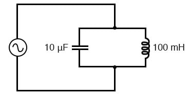
Simple Parallel (Tank Circuit) Resonance :-

  Resonance in a Tank Circuit :- A condition of resonance will be experienced in a tank circuit when the reactance of the capacitor and  ind...