Pages

Translate

Showing posts with label Electrical Machines ( Transformer }. Show all posts

Monday, 6 July 2020

Three-phase Transformer Circuits :-

Three-phase Transformer Circuits :-

Since three-phase is used so often for power distribution systems, it makes sense that we would need three-phase transformers to be able to step voltages up or down.

This is only partially true, as regular single-phase transformers can be ganged together to transform power between two three-phase systems in a variety of configurations, eliminating the requirement for a special three-phase transformer.

However, special three-phase transformers are built for those tasks and are able to perform with less material requirement, less size, and less weight than their modular counterparts.

Three-Phase Transformer Windings and Connections :-

A three-phase transformer is made of three sets of primary and secondary windings, each set wound around one leg of an iron core assembly. Essentially it looks like three single-phase transformers sharing a joined core as in Figure below.


Three phase transformer core has three sets of windings.

Three phase transformer core has three sets of windings.


Those sets of primary and secondary windings will be connected in either Δ or Y configurations to form a complete unit. The various combinations of ways that these windings can be connected together it will be the focus of this section.

Whether the winding sets share a common core assembly or each winding pair is a separate transformer, the winding connection options are the same:


Primary - Secondary

  • Y - Y
  • Y - Δ
  • Δ - Y
  • Δ - Δ


The reasons for choosing a Y or Δ configuration for transformer winding connections are the same as for any other three-phase application: Y connections provide the opportunity for multiple voltages, while Δ connections enjoy a higher level of reliability (if one winding fails open, the other two can still maintain full line voltages to the load).

Probably the most important aspect of connecting three sets of primary and secondary windings together to form a three-phase transformer bank is paying attention to proper winding phasing (the dots used to denote “polarity” of windings).

Remember the proper phase relationships between the phase windings of Δ and Y: (Figure below)


(Y) The center point of the “Y” must tie either all the “-” or all the “+” winding points together. (Δ) The winding polarities must stack together in a complementary manner ( + to -).

(Y) The center point of the “Y” must tie either all the “-” or all the “+” winding points together. (Δ) The winding polarities must stack together in a complementary manner ( + to -).


Getting this phasing correct when the windings aren’t shown in regular Y or Δ configuration can be tricky. Let me illustrate, starting with the figure below.


Inputs A1, A2, A3 may be wired either “Δ” or “Y”, as may outputs B1, B2, B3.

Inputs A1, A2, A3 may be wired either “Δ” or “Y”, as may outputs B1, B2, B3.


Phase Wiring for “Y-Y” Transformer :-

Three individual transformers are to be connected together to transform power from one three-phase system to another. First, I’ll show the wiring connections for a Y-Y configuration:


Phase wiring for “Y-Y” transformer.

Phase wiring for “Y-Y” transformer.


Note in Figure above how all the winding ends marked with dots are connected to their respective phases A, B, and C, while the non-dot ends are connected together to form the centers of each “Y”.

Having both primary and secondary winding sets connected in “Y” formations allows for the use of neutral conductors (N1 and N2) in each power system.

Phase Wiring for “Y-Δ” Transformer :-

Now, we’ll take a look at a Y-Δ configuration:


Phase wiring for “Y-Δ” transformer.

Phase wiring for “Y-Δ” transformer.


Note how the secondary windings (bottom set, Figure above) are connected in a chain, the “dot” side of one winding connected to the “non-dot” side of the next, forming the Δ loop.

At every connection point between pairs of windings, a connection is made to a line of the second power system (A, B, and C).

Phase Wiring for “Δ-Y” Transformer :-

Now, let’s examine a Δ-Y system in the figure below.


Phase wiring for “Δ-Y” transformer.

Phase wiring for “Δ-Y” transformer.


Such a configuration (Figure above) would allow for the provision of multiple voltages (line-to-line or line-to-neutral) in the second power system, from a source power system having no neutral.

Phase Wiring for “Δ-Δ” Transformer :-

And finally, we turn to the Δ-Δ configuration:


Phase wiring for “Δ-Δ” transformer.

Phase wiring for “Δ-Δ” transformer.


When there is no need for a neutral conductor in the secondary power system, Δ-Δ connection schemes (Figure above) are preferred because of the inherent reliability of the Δ configuration.

Phase Wiring for “V” or “open-Δ” Transformer :-

Considering that a Δ configuration can operate satisfactorily missing one winding, some power system designers choose to create a three-phase transformer bank with only two transformers, representing a Δ-Δ configuration with a missing winding in both the primary and secondary sides:


“V” or “open-Δ” provides 2-φ power with only two transformers.

“V” or “open-Δ” provides 2-φ power with only two transformers.


This configuration is called “V” or “Open-Δ.” Of course, each of the two transformers has to be oversized to handle the same amount of power as three in a standard Δ configuration, but the overall size, weight, and cost advantages are often worth it.

Bear in mind, however, that with one winding set missing from the Δ shape, this system no longer provides the fault tolerance of a normal Δ-Δ system. If one of the two transformers were to fail, the load voltage and current would definitely be affected.

Real Life Example :-

The following photograph (figure below) shows a bank of step-up transformers at the Grand Coulee hydroelectric dam in Washington state.

Several transformers (green in color) may be seen from this vantage point, and they have grouped in threes: three transformers per hydroelectric generator, wired together in some form of three-phase configuration.

The photograph doesn’t reveal the primary winding connections, but it appears the secondaries are connected in a Y configuration, is that there is only one large high-voltage insulator protruding from each transformer.

This suggests the other side of each transformer’s secondary winding is at or near ground potential, which could only be true in a Y system.

The building to the left is the powerhouse, where the generators and turbines are housed. On the right, the sloping concrete wall is the downstream face of the dam:


grand coulee hydroelectric dam


Wednesday, 1 July 2020

Practical Considerations - Transformers :-

Power Capacity :-

As has already been observed, transformers must be well designed in order to achieve acceptable power coupling, tight voltage regulation, and low exciting current distortion. Also, transformers must be designed to carry the expected values of primary and secondary winding current without any trouble.

This means the winding conductors must be made of the proper gauge wire to avoid any heating problems.

Ideal Transformer :-

An ideal transformer would have perfect coupling (no leakage inductance), perfect voltage regulation, perfectly sinusoidal exciting current, no hysteresis or eddy current losses, and wire thick enough to handle any amount of current. Unfortunately, the ideal transformer would have to be infinitely large and heavy to meet these design goals.

Thus, in the business of practical transformer design, compromises must be made.

Additionally, winding conductor insulation is a concern where high voltages are encountered, as they often are in step-up and step-down power distribution transformers.

Not only do the windings have to be well insulated from the iron core, but each winding has to be sufficiently insulated from the other in order to maintain electrical isolation between windings.

Transformer Ratings :-

Respecting these limitations, transformers are rated for certain levels of primary and secondary winding voltage and current, though the current rating is usually derived from a volt-amp (VA) rating assigned to the transformer.

For example, take a step-down transformer with a primary voltage rating of 120 volts, a secondary voltage rating of 48 volts, and a VA rating of 1 kVA (1000 VA). The maximum winding currents can be determined as such:kVA (1000 VA). The maximum winding currents can be determined as such:


maximum winding currents formula


Sometimes windings will bear current ratings in amps, but this is typically seen on small transformers. Large transformers are almost always rated in terms of winding voltage and VA or kVA.kVA.

Energy Losses :-

When transformers transfer power, they do so with a minimum of loss. As it was stated earlier, modern power transformer designs typically exceed 95% efficiency. It is good to know where some of this lost power goes, however, and what causes it to be lost.

There is, of course, power loss due to the resistance of the wire windings. Unless superconducting wires are used, there will always be power dissipated in the form of heat through the resistance of current-carrying conductors. Because transformers require such long lengths of wire, this loss can be a significant factor.

Increasing the gauge of the winding wire is one way to minimize this loss, but only with substantial increases in cost, size, and weight.

Eddy-Current Loss :-

Resistive losses aside, the bulk of transformer power loss is due to magnetic effects in the core. Perhaps the most significant of these “core losses” is an eddy-current loss, which is resistive power dissipation due to the passage of induced currents through the iron of the core.

Because iron is a conductor of electricity as well as being an excellent “conductor” of magnetic flux, there will be currents induced in the iron just as there are currents induced in the secondary windings from the alternating magnetic field.

These induced currents—as described by the perpendicularity clause of Faraday’s Law —tend to circulate through the cross-section of the core perpendicularly to the primary winding turns.

Their circular motion gives them their unusual name: like eddies in a stream of water that circulate rather than move in straight lines.

Iron is a fair conductor of electricity, but not as good as the copper or aluminum from which wire windings are typically made. Consequently, these “eddy currents” must overcome significant electrical resistance as they circulate through the core.

In overcoming the resistance offered by the iron, they dissipate power in the form of heat. Hence, we have a source of inefficiency in the transformer that is difficult to eliminate.

Induction Heating :-

This phenomenon is so pronounced that it is often exploited as a means of heating ferrous (iron-containing) materials. The photograph below shows an “induction heating” unit raising the temperature of a large pipe section.

Loops of wire covered by high-temperature insulation encircle the pipe’s circumference, inducing eddy currents within the pipe wall by electromagnetic induction. In order to maximize the eddy current effect, high-frequency alternating current is used rather than power line frequency (60 Hz).

The box units at the right of the picture produce the high-frequency AC and control the amount of current in the wires to stabilize the pipe temperature at a pre-determined “set-point.”


Induction heating: Primary insulated winding induces current into lossy iron pipe (secondary).

Induction heating: Primary insulated winding induces current into the lossy iron pipe (secondary).


Mitigating Eddy Currents :-

The main strategy in mitigating these wasteful eddy currents in transformer cores is to form the iron core in sheets, each sheet covered with an insulating varnish so that the core is divided up into thin slices. The result is very little width in the core for eddy currents to circulate in:


Dividing the iron core into thin insulated laminations minimizes eddy current loss.

Dividing the iron core into thin insulated laminations minimizes eddy current loss.


Laminated cores like the one shown here are standard in almost all low-frequency transformers. Recall from the photograph of the transformer cut in half that the iron core was composed of many thin sheets rather than one solid piece.

Eddy current losses increase with frequency, so transformers designed to run on higher-frequency power (such as 400 Hz, used in many military and aircraft applications) must use thinner laminations to keep the losses down to a respectable minimum.

This has the undesirable effect of increasing the manufacturing cost of the transformer.

Another, similar technique for minimizing eddy current losses which work better for high-frequency applications is to make the core out of iron powder instead of thin iron sheets.

Like the lamination sheets, these granules of iron are individually coated in an electrically insulating material, which makes the core nonconductive except for within the width of each granule. Powdered iron cores are often found in transformers handling radio-frequency currents.

Magnetic Hysteresis :-

Another “core loss” is that of magnetic hysteresis. All ferromagnetic materials tend to retain some degree of magnetization after exposure to an external magnetic field.

This tendency to stay magnetized is called “hysteresis,” and it takes a certain investment in energy to overcome this opposition to change every time the magnetic field produced by the primary winding changes polarity (twice per AC cycle).

This type of loss can be mitigated through good core material selection (choosing a core alloy with low hysteresis, as evidenced by a “thin” B/H hysteresis curve), and designing the core for minimum flux density (large cross-sectional area).

Skin Effect at High Frequencies :-

Transformer energy losses tend to worsen with increasing frequency. The skin effect within winding conductors reduces the available cross-sectional area for electric charge flow, thereby increasing effective resistance as the frequency goes up and creating more power lost through resistive dissipation.

Magnetic core losses are also exaggerated with higher frequencies, eddy currents, and hysteresis effects becoming more severe. For this reason, transformers of significant size are designed to operate efficiently in a limited range of frequencies.

In most power distribution systems where the line frequency is very stable, one would think excessive frequency would never pose a problem. Unfortunately, it does, in the form of harmonics created by nonlinear loads.

As we’ve seen in earlier chapters, nonsinusoidal waveforms are equivalent to additive series of multiple sinusoidal waveforms at different amplitudes and frequencies. In power systems, these other frequencies are whole-number multiples of the fundamental (line) frequency, meaning that they will always be higher, not lower, than the design frequency of the transformer.

In significant measure, they can cause severe transformer overheating. Power transformers can be engineered to handle certain levels of power system harmonics, and this capability is sometimes denoted with a “K factor” rating.

Stray Capacitance and Inductance :-

Aside from power ratings and power losses, transformers often harbor other undesirable limitations that circuit designers must be made aware of. Like their simpler counterparts—inductors—transformers exhibit capacitance due to the insulation dielectric between conductors: from winding to winding, turn to turn (in a single winding), and winding to the core.

Transformer Resonance Frequency :-

Usually, this capacitance is of no concern in a power application, but small signal applications (especially those of high frequency) may not tolerate this quirk well.

Also, the effect of having capacitance along with the windings’ designed inductance gives transformers the ability to resonate at a particular frequency, definitely a design concern in signal applications where the applied frequency may reach this point (usually the resonant frequency of a power transformer is well beyond the frequency of the AC power it was designed to operate on).

Flux Containment :-

Flux containment (making sure a transformer’s magnetic flux doesn’t escape so as to interfere with another device, and making sure other devices’ magnetic flux is shielded from the transformer core) is another concern shared both by inductors and transformers.

Leakage Inductance :-

Closely related to the issue of flux containment is leakage inductance. We’ve already seen the detrimental effects of leakage inductance on voltage regulation with SPICE simulations early in this chapter. Because leakage inductance is equivalent to an inductance connected in series with the transformer’s winding, it manifests itself as a series impedance with the load.

Thus, the more current drawn by the load, the less voltage available at the secondary winding terminals. Usually, good voltage regulation is desired in transformer design, but there are exceptional applications.

As was stated before, discharge lighting circuits require a step-up transformer with “loose” (poor) voltage regulation to ensure reduced voltage after the establishment of an arc through the lamp. One way to meet this design criterion is to engineer the transformer with flux leakage paths for magnetic flux to bypass the secondary winding(s).

The resulting leakage flux will produce leakage inductance, which will, in turn, produce the poor regulation needed for discharge lighting.

Core Saturation :-

Transformers are also constrained in their performance by the magnetic flux limitations of the core. For ferromagnetic core transformers, we must be mindful of the saturation limits of the core.

Remember that ferromagnetic materials cannot support infinite magnetic flux densities: they tend to “saturate” at a certain level (dictated by the material and core dimensions), meaning that further increases in magnetic field force (mmf) do not result in proportional increases in magnetic field flux (Φ).

When a transformer’s primary winding is overloaded from excessive applied voltage, the core flux may reach saturation levels during peak moments of the AC sine wave cycle. If this happens, the voltage induced in the secondary winding will no longer match the wave-shape as the voltage powering the primary coil.

In other words, the overloaded transformer will distort the waveshape from primary to secondary windings, creating harmonics in the secondary winding’s output. As we discussed before, harmonic content in AC power systems typically causes problems.

Peaking Transformers :-

Special transformers known as peaking transformers exploit this principle to produce brief voltage pulses near the peaks of the source voltage waveform. The core is designed to saturate quickly and sharply, at voltage levels well below peak.

This results in a severely cropped sine-wave flux waveform, and secondary voltage pulses only when the flux is changing (below saturation levels):


Voltage and flux waveforms for a peaking transformer.

Voltage and flux waveforms for a peaking transformer.


Operation at Frequencies Lower than Normal :-

Another cause of abnormal transformer core saturation is operation at frequencies lower than normal. For example, if a power transformer designed to operate at 60 Hz is forced to operate at 50 Hz instead, the flux must reach greater peak levels than before in order to produce the same opposing voltage needed to balance against the source voltage.

This is true even if the source voltage is the same as before.


Magnetic flux is higher in a transformer core driven by 50 Hz as compared to 60 Hz for the same voltage.

Magnetic flux is higher in a transformer core driven by 50 Hz as compared to 60 Hz for the same voltage.


Since instantaneous winding voltage is proportional to the instantaneous magnetic flux’s rate of change in a transformer, a voltage waveform reaching the same peak value, but taking a longer amount of time to complete each half-cycle, demands that the flux maintain the same rate of change as before, but for longer periods of time.

Thus, if the flux has to climb at the same rate as before, but for longer periods of time, it will climb to a greater peak value.

Mathematically, this is another example of calculus in action. Because the voltage is proportional to the flux’s rate-of-change, we say that the voltage waveform is the derivative of the flux waveform, “derivative” being that calculus operation defining one mathematical function (waveform) in terms of the rate-of-change of another.

If we take the opposite perspective, though, and relate the original waveform to its derivative, we may call the original waveform the integral of the derivative waveform. In this case, the voltage waveform is the derivative of the flux waveform, and the flux waveform is the integral of the voltage waveform.

The integral of any mathematical function is proportional to the area accumulated underneath the curve of that function. Since each half-cycle of the 50 Hz waveform accumulates more area between it and the zero line of the graph than the 60 Hz waveform will—and we know that the magnetic flux is the integral of the voltage—the flux will attain higher values in the Figure below.


Flux changing at the same rate rises to a higher level at 50 Hz than at 60 Hz.

Flux changing at the same rate rises to a higher level at 50 Hz than at 60 Hz.


Yet another cause of transformer saturation is the presence of DC current in the primary winding. Any amount of DC voltage dropped across the primary winding of a transformer will cause an additional magnetic flux in the core. This additional flux “bias” or “offset” will push the alternating flux waveform closer to saturation in one half-cycle than the other.


DC in primary, shifts the waveform peaks toward the upper saturation limit.

DC in primary shifts the waveform peaks toward the upper saturation limit.


For most transformers, core saturation is a very undesirable effect, and it is avoided through good design: engineering the windings and core so that magnetic flux densities remain well below the saturation levels.

This ensures that the relationship between mmf and Φ is more linear throughout the flux cycle, which is good because it makes for less distortion in the magnetization current waveform.

Also, engineering the core for low flux densities provides a safe margin between the normal flux peaks and the core saturation limits to accommodate occasional, abnormal conditions such as frequency variation and DC offset.

Inrush Current :-

When a transformer is initially connected to a source of AC voltage, there may be a substantial surge of current through the primary winding called inrush current. This is analogous to the inrush current exhibited by an electric motor that is started up by sudden connection to a power source, although transformer inrush is caused by a different phenomenon.

We know that the rate of change of instantaneous flux in a transformer core is proportional to the instantaneous voltage drop across the primary winding. Or, as stated before, the voltage waveform is the derivative of the flux waveform, and the flux waveform is the integral of the voltage waveform.

In a continuously-operating transformer, these two waveforms are phase-shifted by 90°. Since flux (Φ) is proportional to the magnetomotive force (mmf) in the core, and the mmf is proportional to winding current, the current waveform will be in-phase with the flux waveform, and both will be lagging the voltage waveform by 90°:


Continuous steady-state operation: Magnetic flux, like current, lags applied voltage by 90°.

Continuous steady-state operation: Magnetic flux, like current, lags applied voltage by 90°.


Let us suppose that the primary winding of a transformer is suddenly connected to an AC voltage source at the exact moment in time when the instantaneous voltage is at its positive peak value.

In order for the transformer to create an opposing voltage drop to balance against this applied source voltage, a magnetic flux of rapidly increasing value must be generated. The result is that winding current increases rapidly, but actually no more rapidly than under normal conditions:


Connecting transformer to line at AC volt peak: Flux increases rapidly from zero, same as steady-state operation.

Connecting the transformer to the line at AC volt peak: Flux increases rapidly from zero, same as steady-state operation.


Both core flux and coil current start from zero and build up to the same peak values experienced during continuous operation. Thus, there is no “surge” or “inrush” or current in this scenario.

Alternatively, let us consider what happens if the transformer’s connection to the AC voltage source occurs at the exact moment in time when the instantaneous voltage is at zero.

During continuous operation (when the transformer has been powered for quite some time), this is the point in time where both flux and winding current are at their negative peaks, experiencing zero rate-of-change (dΦ/dt = 0 and di/dt = 0).

As the voltage builds to its positive peak, the flux and current waveforms build to their maximum positive rates-of-change, and on upward to their positive peaks as the voltage descends to a level of zero:


Starting at e=0 V is not the same as running continuously in Figure above. These expected waveforms are incorrect– Φ and i should start at zero.

Starting at e=0 V is not the same as running continuously in Figure above. These expected waveforms are incorrect– Φ and I should start at zero.


A significant difference exists, however, between continuous-mode operation and the sudden starting condition assumed in this scenario: during continuous operation, the flux and current levels were at their negative peaks when voltage was at its zero points; in a transformer that has been sitting idle, however, both magnetic flux and winding current should start at zero.

When the magnetic flux increases in response to a rising voltage, it will increase from zero upward, not from a previously negative (magnetized) condition as we would normally have in a transformer that’s been powered for a while.

Thus, in a transformer that’s just “starting,” the flux will reach approximately twice its normal peak magnitude as it “integrates” the area under the voltage waveform’s first half-cycle:


Starting at e=0 V, Φ starts at initial condition Φ=0, increasing to twice the normal value, assuming it doesn’t saturate the core.

Starting at e=0 V, Φ starts at initial condition Φ=0, increasing to twice the normal value, assuming it doesn’t saturate the core.


In an ideal transformer, the magnetizing current would rise to approximately twice its normal peak value as well, generating the necessary mmf to create this higher-than-normal flux.

However, most transformers aren’t designed with enough of a margin between normal flux peaks and the saturation limits to avoid saturating in a condition like this, and so the core will almost certainly saturate during this first half-cycle of voltage.

During saturation, disproportionate amounts of mmf are needed to generate magnetic flux. This means that winding current, which creates the mmf to cause a flux in the core, will disproportionately rise to a value easily exceeding twice its normal peak:


Starting at e=0 V, Current also increases to twice the normal value for an unsaturated core, or considerably higher in the (designed for) case of saturation.

Starting at e=0 V, Current also increases to twice the normal value for an unsaturated core, or considerably higher in the (designed for) case of saturation.


This is the mechanism causing inrush current in a transformer’s primary winding when connected to an AC voltage source. As you can see, the magnitude of the inrush current strongly depends on the exact time that electrical connection to the source is made.

If the transformer happens to have some residual magnetism in its core at the moment of connection to the source, the inrush could be even more severe. Because of this, transformer overcurrent protection devices are usually of the “slow-acting” variety, so as to tolerate current surges such as this without opening the circuit.

Heat and Noise :-

In addition to unwanted electrical effects, transformers may also exhibit undesirable physical effects, the most notable being the production of heat and noise. Noise is primarily a nuisance effect, but heat is a potentially serious problem because winding insulation will be damaged if allowed to overheat.

Heating may be minimized by good design, ensuring that the core does not approach saturation levels, that eddy currents are minimized, and that the windings are not overloaded or operated too close to maximum ampacity.

Large power transformers have their core and windings submerged in an oil bath to transfer heat and muffle noise, and also to displace moisture which would otherwise compromise the integrity of the winding insulation.

Heat-dissipating “radiator” tubes on the outside of the transformer case provide a convective oil flow path to transfer heat from the transformer’s core to ambient air:


Large power transformers are submerged in heat dissipating insulating oil.

Large power transformers are submerged in heat dissipating insulating oil.


Oil-less, or “dry,” transformers are often rated in terms of maximum operating temperature “rise” (temperature increase beyond ambient) according to a letter-class system: A, B, F, or H. These letter codes are arranged in order of lowest heat tolerance to highest:

  • Class A: No more than 55° Celsius winding temperature rise, at 40° Celsius (maximum) ambient air temperature.
  • Class B: No more than 80° Celsius winding temperature rise, at 40° Celsius (maximum)ambient air temperature.
  • Class F: No more than 115° Celsius winding temperature rise, at 40° Celsius (maximum)ambient air temperature.
  • Class H: No more than 150° Celsius winding temperature rise, at 40° Celsius (maximum)ambient air temperature.

Audible noise is an effect primarily originating from the phenomenon of magnetostriction: the slight change of length exhibited by a ferromagnetic object when magnetized.

The familiar “hum” heard around large power transformers is the sound of the iron core expanding and contracting at 120 Hz (twice the system frequency, which is 60 Hz in the United States)—one cycle of core contraction and expansion for every peak of the magnetic flux waveform—plus noise created by mechanical forces between primary and secondary windings.

Again, maintaining low magnetic flux levels in the core is the key to minimizing this effect, which explains why ferroresonant transformers—which must operate in saturation for a large portion of the current waveform—operate both hot and noisy.

Losses due to Winding Magnetic Forces :-

Another noise-producing phenomenon in power transformers is the physical reaction force between primary and secondary windings when heavily loaded.

If the secondary winding is open-circuited, there will be no current through it, and consequently, no magneto-motive force (mmf) produced by it. However, when the secondary is “loaded” (currently supplied to a load), the winding generates an mmf, which becomes counteracted by a “reflected” mmf in the primary winding to prevent core flux levels from changing.

These opposing mmf’s generated between primary and secondary windings as a result of secondary (load) current produce a repulsive, physical force between the windings which will tend to make them vibrate.

Transformer designers have to consider these physical forces in the construction of the winding coils, to ensure there is adequate mechanical support to handle the stresses. Under heavy load (high current) conditions, though, these stresses may be great enough to cause audible noise to emanate from the transformer.


REVIEW :-

  • Power transformers are limited in the amount of power they can transfer from primary to secondary winding(s). Large units are typically rated in VA (volt-amps) or kVA (kilo volt-amps).
  • Resistance in transformer windings contributes to inefficiency, as current will dissipate heat, wasting energy.
  • Magnetic effects in a transformer’s iron core also contribute to inefficiency. Among the effects are eddy currents (circulating induction currents in the iron core) and hysteresis (power lost due to overcoming the tendency of iron to magnetize in a particular direction).
  • Increased frequency results in increased power losses within a power transformer. The presence of harmonics in a power system is a source of frequencies significantly higher than normal, which may cause overheating in large transformers.
  • Both transformers and inductors harbor certain unavoidable amounts of capacitance due to wire insulation (dielectric) separating winding turns from the iron core and from each other. This capacitance can be significant enough to give the transformer a natural resonant frequency, which can be problematic in signal applications.
  • Leakage inductance is caused by magnetic flux not being 100% coupled between windings in a transformer. Any flux not involved with transferring energy from one winding to another will store and release energy, which is how (self-) inductance works. Leakage inductance tends to worsen a transformer’s voltage regulation (secondary voltage “sags” more for a given amount of load current).
  • Magnetic saturation of a transformer core may be caused by excessive primary voltage, operation at too low of a frequency, and/or by the presence of a DC current in any of the windings. Saturation may be minimized or avoided by conservative design, which provides an adequate margin of safety between peak magnetic flux density values and the saturation limits of the core.
  • Transformers often experience significant inrush currents when initially connected to an AC voltage source. Inrush current is most severe when the connection to the AC source is made at the moment instantaneous source voltage is zero.
  • Noise is a common phenomenon exhibited by transformers—especially power transformers—and is primarily caused by magnetostriction of the core. Physical forces causing winding vibration may also generate noise under conditions of heavy (high current) secondary winding load.

Tuesday, 30 June 2020

Special Transformers and Applications :-

Impedance Matching :-

Because transformers can step voltage and current to different levels, and because power is transferred equivalently between primary and secondary windings, they can be used to “convert” the impedance of a load to a different level. That last phrase deserves some explanation, so let’s investigate what it means.

The purpose of a load (usually) is to do something productive with the power it dissipates. In the case of a resistive heating element, the practical purpose for the power dissipated is to heat something up.

Loads are engineered to safely dissipate a certain maximum amount of power, but two loads of equal power ratings are not necessarily identical. Consider these two 1000 watt resistive heating elements:


Heating elements dissipate 1000 watts, at different voltage and current ratings.

Heating elements dissipate 1000 watts, at different voltage and current ratings.


Both heaters dissipate exactly 1000 watts of power, but they do so at different voltage and current levels (either 250 volts and 4 amps, or 125 volts and 8 amps). Using Ohm’s Law to determine the necessary resistance of these heating elements (R=E/I), we arrive at figures of 62.5 Ω and 15.625 Ω, respectively.

If these are AC loads, we might refer to their opposition to current in terms of impedance rather than plain resistance, although in this case, that’s all they’re composed of (no reactance). The 250-volt heater would be said to be a higher impedance load than the 125-volt heater.

If we desire to operate the 250-volt heater element directly on a 125-volt power system, we would end up being disappointed. With 62.5 Ω of impedance (resistance), the current would only be 2 amps (I=E/R; 125/62.5), and the power dissipation would only be 250 watts (P=IE; 125 x 2), or one-quarter of its rated power.

The impedance of the heater and the voltage of our source would be mismatched, and we couldn’t obtain the full rated power dissipation from the heater.

All hope is not lost, though. With a step-up transformer, we could operate the 250 volt heater element on the 125 volt power system like the Figure below.


Step-up transformer operates 1000 watt 250 V heater from 125 V power source.

Step-up transformer operates 1000 watt 250 V heater from 125 V power source.


Impedance, Current and Voltage Transformation Ratios :-

The ratio of the transformer’s windings provides the voltage step-up and current step-down we need for the otherwise mismatched load to operate properly on this system. Take a close look at the primary circuit figures: 125 volts at 8 amps. As far as the power supply “knows,” its powering a 15.625 Ω (R=E/I) load at 125 volts, not a 62.5 Ω load!

The voltage and current figures for the primary winding are indicative of 15.625 Ω load impedance, not the actual 62.5 Ω of the load itself. In other words, not only has our step-up transformer transformed voltage and current, but it has transformed impedance as well.

The transformation ratio of impedance is the square of the voltage/current transformation ratio, the same as the winding inductance ratio:


This concurs with our example of the 2:1 step-up transformer and the impedance ratio of 62.5 Ω to 15.625 Ω (a 4:1 ratio, which is 2:1 squared). Impedance transformation is a highly useful ability of transformers, for it allows a load to dissipate its full rated power even if the power system is not at the proper voltage to directly do so.

Application of Maximum Power Transfer Theorem to Transformers :-

Recall from our study of network analysis the Maximum Power Transfer Theorem, which states that the maximum amount of power will be dissipated by a load resistance when that load resistance is equal to the Thevenin/Norton resistance of the network supplying the power. Substitute the word “impedance” for “resistance” in that definition and you have the AC version of that Theorem.

If we’re trying to obtain theoretical maximum power dissipation from a load, we must be able to properly match the load impedance and source (Thevenin/Norton) impedance together. This is generally more of a concern in specialized electric circuits such as radio transmitter/antenna and audio amplifier/speaker systems.

Let’s take an audio amplifier system and see how it works: (Figure below)


Amplifier with impedance of 500 Ω drives 8 Ω at much less than maximum power.

Amplifier with impedance of 500 Ω drives 8 Ω at much less than maximum power.


With an internal impedance of 500 Ω, the amplifier can only deliver full power to a load (speaker) also having 500 Ω of impedance. Such a load would drop higher voltage and draw less current than an 8 Ω speaker dissipating the same amount of power.

If an 8 Ω speaker were connected directly to the 500 Ω amplifier as shown, the impedance mismatch would result in very poor (low peak power) performance. Additionally, the amplifier would tend to dissipate more than its fair share of power in the form of heat trying to drive the low impedance speaker.

To make this system work better, we can use a transformer to match these mismatched impedances. Since we’re going from a high impedance (high voltage, low current) supply to a low impedance (low voltage, high current) load, we’ll need to use a step-down transformer:


Impedance matching transformer matches 500 Ω amplifier to 8 Ω speaker for maximum efficiency.

Impedance matching transformer matches 500 Ω amplifier to 8 Ω speaker for maximum efficiency.


Description of Impedance Matching :-

To obtain an impedance transformation ratio of 500:8, we would need a winding ratio equal to the square root of 500:8 (the square root of 62.5:1, or 7.906:1).

With such a transformer in place, the speaker will load the amplifier to just the right degree, drawing power at the correct voltage and current levels to satisfy the Maximum Power Transfer Theorem and make for the most efficient power delivery to the load. The use of a transformer in this capacity is called impedance matching.

Anyone who has ridden a multi-speed bicycle can intuitively understand the principle of impedance matching. A human’s legs will produce maximum power when spinning the bicycle crank at a particular speed (about 60 to 90 revolutions per minute).

Above or below that rotational speed, human leg muscles are less efficient at generating power. The purpose of the bicycle’s “gears” is to impedance-match the rider’s legs to the riding conditions so that they always spin the crank at the optimum speed.

If the rider attempts to start moving while the bicycle is shifted into its “top” gear, he or she will find it very difficult to get moving. Is it because the rider is weak?

No, its because the high step-up ratio of the bicycle’s chain and sprockets in that top gear presents a mismatch between the conditions (lots of inertia to overcome) and their legs (needing to spin at 60-90 RPM for maximum power output).

On the other hand, selecting a gear that is too low will enable the rider to get moving immediately, but limit the top speed they will be able to attain. Again, is the lack of speed an indication of weakness in the bicyclist’s legs?

No, its because the lower speed ratio of the selected gear creates another type of mismatch between the conditions (low load) and the rider’s legs (losing power if spinning faster than 90 RPM). It is much the same with electric power sources and loads: there must be an impedance match for maximum system efficiency.

In AC circuits, transformers perform the same matching function as the sprockets and chain (“gears”) on a bicycle to match otherwise mismatched sources and loads.

Impedance Matching Transformers :-

Impedance matching transformers are not fundamentally different from any other type of transformer in construction or appearance. A small impedance-matching transformer (about two centimeters in width) for audio-frequency applications is shown in the following photograph:


Audio frequency impedance matching transformer.

Audio frequency impedance matching transformer.


Another impedance-matching transformer can be seen on this printed circuit board, in the upper right corner, to the immediate left of resistors R2and R1. It is labeled “T1”:


Printed circuit board mounted audio impedance matching transformer, top right.

Printed circuit board mounted audio impedance matching transformer, top right.


Potential Transformers :-

Transformers can also be used in electrical instrumentation systems. Due to transformers’ ability to step up or step down voltage and current, and the electrical isolation they provide, they can serve as a way of connecting electrical instrumentation to high-voltage, high current power systems.

Suppose we wanted to accurately measure the voltage of a 13.8 kV power system (a very common power distribution voltage in American industry):


Direct measurement of high voltage by a voltmeter is a potential safety hazard.

Direct measurement of high voltage by a voltmeter is a potential safety hazard.


Designing, installing, and maintaining a voltmeter capable of directly measuring 13,800 volts AC would be no easy task. The safety hazard alone of bringing 13.8 kV conductors into an instrument panel would be severe, not to mention the design of the voltmeter itself.

However, by using a precision step-down transformer, we can reduce the 13.8 kV down to a safe level of voltage at a constant ratio, and isolate it from the instrument connections, adding an additional level of safety to the metering system:


Instrumentation application:“Potential transformer” precisely scales dangerous high voltage to a safe value applicable to a conventional voltmeter.

Instrumentation application:“Potential transformer” precisely scales dangerous high voltage to a safe value applicable to a conventional voltmeter.


Now the voltmeter reads a precise fraction, or ratio, of the actual system voltage, its scale set to read as though it were measuring the voltage directly.

The transformer keeps the instrument voltage at a safe level and electrically isolates it from the power system, so there is no direct connection between the power lines and the instrument or instrument wiring. When used in this capacity, the transformer is called a Potential Transformer, or simply PT.

Potential transformers are designed to provide as accurate a voltage step-down ratio as possible. To aid in precise voltage regulation, loading is kept to a minimum: the voltmeter is made to have high input impedance so as to draw as little current from the PT as possible.

As you can see, a fuse has been connected in series with the PTs primary winding, for safety and ease of disconnecting the PT from the circuit.

A standard secondary voltage for a PT is 120 volts AC, for full-rated power line voltage. The standard voltmeter range to accompany a PT is 150 volts, full-scale.

PTs with custom winding ratios can be manufactured to suit any application. This lends itself well to industry standardization of the actual voltmeter instruments themselves, since the PT will be sized to step the system voltage down to this standard instrument level.

Current Transformers :-

Following the same line of thinking, we can use a transformer to step down current through a power line so that we are able to safely and easily measure high system currents with inexpensive ammeters. Of course, such a transformer would be connected in series with the power line.
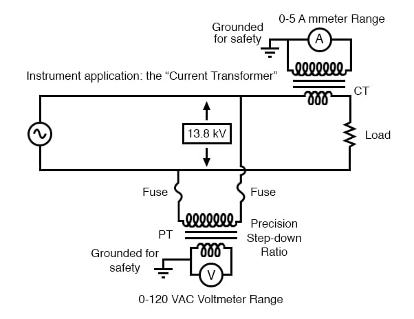
 

Instrumentation application: “Current transformer” steps high current down to a value applicable to a conventional ammeter.

Instrumentation application: “Current transformer” steps high current down to a value applicable to a conventional ammeter.


Note that while the PT is a step-down device, the Current Transformer (or CT) is a step-up device (with respect to voltage), which is what is needed to step down the power line current. Quite often, CTs are built as donut-shaped devices through which the power line conductor is run, the power line itself acting as a single-turn primary winding:


Current conductor to be measured is threaded through the opening. Scaled down current is available on wire leads.

Current conductor to be measured is threaded through the opening. Scaled down current is available on wire leads.


Some CTs are made to hinge open, allowing insertion around a power conductor without disturbing the conductor at all. The industry standard secondary current for a CT is a range of 0 to 5 amps AC. Like PTs, CTs can be made with custom winding ratios to fit almost any application.

Because their “full load” secondary current is 5 amps, CT ratios are usually described in terms of full-load primary amps to 5 amps, like this:


The “donut” CT shown in the photograph has a ratio of 50:5. That is, when the conductor through the center of the torus is carrying 50 amps of current (AC), there will be 5 amps of current induced in the CT’s winding.

Because CTs are designed to be powering ammeters, which are low-impedance loads, and they are wound as voltage step-up transformers, they should never, ever be operated with an open-circuited secondary winding.

Failure to heed this warning will result in the CT producing extremely high secondary voltages, dangerous to equipment and personnel alike. To facilitate maintenance of ammeter instrumentation, short-circuiting switches are often installed in parallel with the CT’s secondary winding, to be closed whenever the ammeter is removed for service:
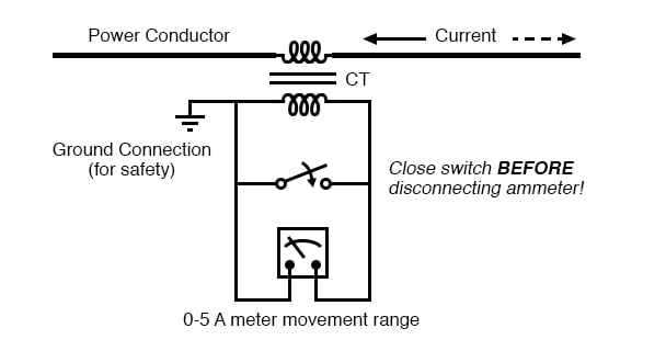
 

Short-circuit switch allows ammeter to be removed from an active current transformer circuit.

Short-circuit switch allows ammeter to be removed from an active current transformer circuit.


Though it may seem strange to intentionally short-circuit a power system component, it is perfectly proper and quite necessary when working with current transformers.

Air Core Transformers :-

Another kind of special transformer, seen often in radio-frequency circuits, is the air core transformer. True to its name, an air core transformer has its windings wrapped around a nonmagnetic form, usually a hollow tube of some material.

The degree of coupling (mutual inductance) between windings in such a transformer is many times less than that of an equivalent iron-core transformer, but the undesirable characteristics of a ferromagnetic core (eddy current losses, hysteresis, saturation, etc.) are completely eliminated.

It is in high-frequency applications that these effects of iron cores are most problematic.


Air core transformers may be wound on cylindrical (a) or toroidal (b) forms. Center tapped primary with secondary (a). Bifilar winding on toroidal form (b).

Air core transformers may be wound on cylindrical (a) or toroidal (b) forms. Center tapped primary with secondary (a). Bifilar winding on toroidal form (b).


The inside tapped solenoid winding, without the over winding, could match unequal impedances when DC isolation is not required. When isolation is required the over winding is added over one end of the main winding. Air core transformers are used at radio frequencies when iron core losses are too high.

Frequently air core transformers are paralleled with a capacitor to tune it to resonance. The over winding is connected between a radio antenna and ground for one such application. The secondary is tuned to resonance with a variable capacitor.

The output may be taken from the tap point for amplification or detection. Small millimeter size air core transformers are used in radio receivers. The largest radio transmitters may use meter sized coils. Unshielded air core solenoid transformers are mounted at right angles to each other to prevent stray coupling.

Stray coupling is minimized when the transformer is wound on a toroid form. Toroidal air core transformers also show a higher degree of coupling, particularly for bifilar windings. Bifilar windings are wound from a slightly twisted pair of wires.

This implies a 1:1 turns ratio. Three or four wires may be grouped for 1:2 and other integral ratios. Windings do not have to be bifilar. This allows arbitrary turns ratios. However, the degree of coupling suffers. Toroidal air core transformers are rare except for VHF (Very High Frequency) work.

Core materials other than air such as powdered iron or ferrite are preferred for lower radio frequencies.

Tesla Coil :-

One notable example of an air-core transformer is the Tesla Coil, named after the Serbian electrical genius Nikola Tesla, who was also the inventor of the rotating magnetic field AC motor, polyphase AC power systems, and many elements of radio technology.

The Tesla Coil is a resonant, high-frequency step-up transformer used to produce extremely high voltages.

One of Tesla’s dreams was to employ his coil technology to distribute electric power without the need for wires, simply broadcasting it in the form of radio waves which could be received and conducted to loads by means of antennas.

The basic schematic for a Tesla Coil is shown in the Figure below.


Tesla Coil: A few heavy primary turns, many secondary turns.

Tesla Coil: A few heavy primary turns, many secondary turns.


The capacitor, in conjunction with the transformer’s primary winding, forms a tank circuit. The secondary winding is wound in close proximity to the primary, usually around the same nonmagnetic form. Several options exist for “exciting” the primary circuit, the simplest being a high-voltage, low-frequency AC source and spark gap:


System level diagram of Tesla coil with spark gap drive.

System level diagram of Tesla coil with spark gap drive.


The purpose of the high-voltage, low-frequency AC power source is to “charge” the primary tank circuit. When the spark gap fires, its low impedance acts to complete the capacitor/primary coil tank circuit, allowing it to oscillate at its resonant frequency.

The “RFC” inductors are “Radio Frequency Chokes,” which act as high impedances to prevent the AC source from interfering with the oscillating tank circuit.

The secondary side of the Tesla coil transformer is also a tank circuit, relying on the parasitic (stray) capacitance existing between the discharge terminal and earth ground to complement the secondary winding’s inductance.

For optimum operation, this secondary tank circuit is tuned to the same resonant frequency as the primary circuit, with energy exchanged not only between capacitors and inductors during resonant oscillation, but also back-and-forth between primary and secondary windings. The visual results are spectacular:


High voltage high frequency discharge from Tesla coil.

High voltage high frequency discharge from Tesla coil.


Tesla Coils find application primarily as novelty devices, showing up in high school science fairs, basement workshops, and the occasional low budget science-fiction movie.

It should be noted that Tesla coils can be extremely dangerous devices. Burns caused by radio-frequency (“RF”) current, like all electrical burns, can be very deep, unlike skin burns caused by contact with hot objects or flames.

Although the high-frequency discharge of a Tesla coil has the curious property of being beyond the “shock perception” frequency of the human nervous system, this does not mean Tesla coils cannot hurt or even kill you! I strongly advise seeking the assistance of an experienced Tesla coil experimenter if you would embark on building one yourself.

Saturable Reactors :-

So far, we’ve explored the transformer as a device for converting different levels of voltage, current, and even impedance from one circuit to another. Now we’ll take a look at it as a completely different kind of device: one that allows a small electrical signal to exert control over a much larger quantity of electrical power. In this mode, a transformer acts as an amplifier.

The device I’m referring to is called a saturable-core reactor, or simply saturable reactor. Actually, it is not really a transformer at all, but rather a special kind of inductor whose inductance can be varied by the application of a DC current through a second winding wound around the same iron core.

Like the ferroresonant transformer, the saturable reactor relies on the principle of magnetic saturation. When a material such as iron is completely saturated (that is, all its magnetic domains are lined up with the applied magnetizing force), additional increases in current through the magnetizing winding will not result in further increases of magnetic flux.

Review on Inductance :-

Now, inductance is the measure of how well an inductor opposes changes in current by developing a voltage in an opposing direction. The ability of an inductor to generate this opposing voltage is directly connected with the change in magnetic flux inside the inductor resulting from the change in current, and the number of winding turns in the inductor.

If an inductor has a saturated core, no further magnetic flux will result from further increases in current, and so there will be no voltage induced in opposition to the change in current. In other words, an inductor loses its inductance (ability to oppose changes in current) when its core becomes magnetically saturated.

If an inductor’s inductance changes, then its reactance (and impedance) to AC current changes as well. In a circuit with a constant voltage source, this will result in a change in current:


If L changes in inductance, ZL will correspondingly change, thus changing the circuit current.


Saturable Reactor Operation :-

A saturable reactor capitalizes on this effect by forcing the core into a state of saturation with a strong magnetic field generated by current through another winding. The reactor’s “power” winding is the one carrying the AC load current, and the “control” winding is one carrying a DC current strong enough to drive the core into saturation:


DC, via the control winding, saturates the core. Thus, modulating the power winding inductance, impedance, and current.

DC, via the control winding, saturates the core. Thus, modulating the power winding inductance, impedance, and current.


The strange-looking transformer symbol shown in the above schematic represents a saturable-core reactor, the upper winding being the DC control winding and the lower being the “power” winding through which the controlled AC current goes.

Increased DC control current produces more magnetic flux in the reactor core, driving it closer to a condition of saturation, thus decreasing the power winding’s inductance, decreasing its impedance, and increasing current to the load. Thus, the DC control current is able to exert control over the AC current delivered to the load.

The circuit shown would work, but it would not work very well. The first problem is the natural transformer action of the saturable reactor: AC current through the power winding will induce a voltage in the control winding, which may cause trouble for the DC power source.

Also, saturable reactors tend to regulate AC power only in one direction: in one half of the AC cycle, the mmf’s from both windings add; in the other half, they subtract. Thus, the core will have more flux in it during one half of the AC cycle than the other and will saturate first in that cycle half, passing load current more easily in one direction than the other.

Fortunately, both problems can be overcome with a little ingenuity:
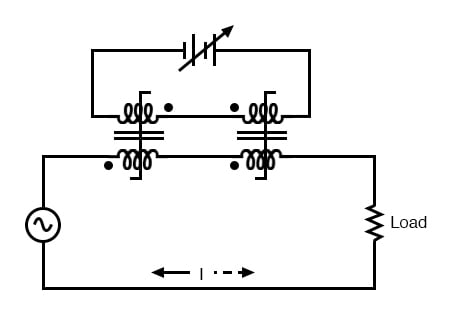
 

Out of phase DC control windings allow symmetrical of control AC.

Out of phase DC control windings allow symmetrical of control AC.


Notice the placement of the phasing dots on the two reactors: the power windings are “in phase” while the control windings are “out of phase.” If both reactors are identical, any voltage induced in the control windings by load current through the power windings will cancel out to zero at the battery terminals, thus eliminating the first problem mentioned.

Furthermore, since the DC control current through both reactors produces magnetic fluxes in different directions through the reactor cores, one reactor will saturate more in one cycle of the AC power while the other reactor will saturate more in the other, thus equalizing the control action through each half-cycle so that the AC power is “throttled” symmetrically.

This phasing of control windings can be accomplished with two separate reactors as shown, or in a single reactor design with intelligent layout of the windings and core.

Saturable reactor technology has even been miniaturized to the circuit-board level in compact packages more generally known as magnetic amplifiers.

I personally find this to be fascinating: the effect of amplification (one electrical signal controlling another), normally requiring the use of physically fragile vacuum tubes or electrically “fragile” semiconductor devices, can be realized in a device both physically and electrically rugged.

Magnetic amplifiers do have disadvantages over their more fragile counterparts, namely size, weight, nonlinearity, and bandwidth (frequency response), but their utter simplicity still commands a certain degree of appreciation, if not practical application.

Saturable-core reactors are less commonly known as “saturable-core inductors” or transductors.

Scott-T Transformer :-

Nikola Tesla’s original polyphase power system was based on simple to build 2-phase components. However, as transmission distances increased, the more transmission line efficient 3-phase system became more prominent. Both 2-φ and 3-φ components coexisted for a number of years.

The Scott-T transformer connection allowed 2-φ and 3-φ components like motors and alternators to be interconnected. Yamamoto and Yamaguchi:

In 1896, General Electric built a 35.5 km (22 mi) three-phase transmission line operated at 11 kV to transmit power to Buffalo, New York, from the Niagara Falls Project. The two-phase generated power was changed to three-phase by the use of Scott-T transformations.


Scott-T transformer converts 2-φ to 3-φ, or vice versa.

Scott-T transformer converts 2-φ to 3-φ, or vice versa.


The Scott-T transformer set, Figure above, consists of a center tapped transformer T1 and an 86.6% tapped transformer T2 on the 3-φ side of the circuit. The primaries of both transformers are connected to the 2-φ voltages.

One end of the T2 86.6% secondary winding is a 3-φ output, the other end is connected to the T1 secondary center tap. Both ends of the T1 secondary are the other two 3-φ connections.

Application of 2-φ Niagara generator power produced a 3-φ output for the more efficient 3-φ transmission line. More common these days is the application of 3-φ power to produce a 2-φ output for driving an old 2-φ motor.

In the Figure below, we use vectors in both polar and complex notation to prove that the Scott-T converts a pair of 2-φ voltages to 3-φ. First, one of the 3-φ voltages is identical to a 2-φ voltage due to the 1:1 transformer T1 ratio, VP12= V2P1.

The T1 center tapped secondary produces opposite polarities of 0.5V2P1 on the secondary ends.

This ∠0° is vectorially subtracted from T2 secondary voltage due to the KVL equations V31, V23.

The T2 secondary voltage is 0.866V2P2 due to the 86.6% tap. Keep in mind that this 2nd phase of the 2-φ is ∠90°. This 0.866V2P2 is added at V31, subtracted at V23 in the KVL equations.


Scott-T transformer 2-φ to 3-φ conversion equations.

Scott-T transformer 2-φ to 3-φ conversion equations.


We show “DC” polarities all over this AC only circuit, to keep track of the Kirchhoff voltage loop polarities. Subtracting ∠0° is equivalent to adding ∠180°. The bottom line is when we add 86.6% of ∠90° to 50% of ∠180°we get ∠120°. Subtracting 86.6% of ∠90° from 50% of ∠180° yields ∠-120° or ∠240°.


Graphical explanation of equations in Figure previous.

Graphical explanation of equations in Figure previous.


In Figure above we graphically show the 2-φ vectors at (a). At (b) the vectors are scaled by transformers T1 and T2 to 0.5 and 0.866 respectively. At (c) 1∠120° = -0.5∠0° + 0.866∠90°, and 1∠240° = -0.5∠0° - 0.866∠90°. The three output phases are 1∠120° and 1∠240° from (c), along with input 1∠0° (a).

Linear Variable Differential Transformer :-

linear variable differential transformer (LVDT) has an AC driven primary wound between two secondaries on a cylindrical air core form (figure below). A movable ferromagnetic slug converts the displacement to a variable voltage by changing the coupling between the driven primary and secondary windings.

The LVDT is a displacement or distance measuring transducer. Units are available for measuring displacement over a distance of a fraction of a millimeter to a half a meter. LVDT’s are rugged and dirt resistant compared to linear optical encoders.


LVDT: linear variable differential transformer.

LVDT: linear variable differential transformer.


The excitation voltage is in the range of 0.5 to 10 VAC at a frequency of 1 to 200 Khz. A ferrite core is suitable at these frequencies. It is extended outside the body by an non-magnetic rod. As the core is moved toward the top winding, the voltage across this coil increases due to increased coupling, while the voltage on the bottom coil decreases.

If the core is moved toward the bottom winding, the voltage on this coil increases as the voltage decreases across the top coil. Theoretically, a centered slug yields equal voltages across both coils. In practice leakage inductance prevents the null from dropping all the way to 0 V.

With a centered slug, the series-opposing wired secondaries cancel yielding V13 = 0. Moving the slug up increases V13. Note that it is in-phase with with V1, the top winding, and 180° out of phase with V3, bottom winding.

Moving the slug down from the center position increases V13. However, it is 180° out of phase with with V1, the top winding, and in-phase with V3, bottom winding. Moving the slug from top to bottom shows a minimum at the center point, with a 180° phase reversal in passing the center.


REVIEW :-

  • Transformers can be used to transform impedance as well as voltage and current. When this is done to improve power transfer to a load, it is called impedance matching.
  • Potential Transformer (PT) is a special instrument transformer designed to provide a precise voltage step-down ratio for voltmeters measuring high power system voltages.
  • Current Transformer (CT) is another special instrument transformer designed to step down the current through a power line to a safe level for an ammeter to measure.
  • An air-core transformer is one lacking a ferromagnetic core.
  • Tesla Coil is a resonant, air-core, step-up transformer designed to produce very high AC voltages at high frequency.
  • saturable reactor is a special type of inductor, the inductance of which can be controlled by the DC current through a second winding around the same core. With enough DC current, the magnetic core can be saturated, decreasing the inductance of the power winding in a controlled fashion.
  • Scott-T transformer converts 3-φ power to 2-φ power and vice versa.
  • linear variable differential transformer, also known as an LVDT, is a distance measuring device. It has a movable ferromagnetic core to vary the coupling between the excited primary and a pair of secondaries.

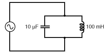
Simple Parallel (Tank Circuit) Resonance :-

  Resonance in a Tank Circuit :- A condition of resonance will be experienced in a tank circuit when the reactance of the capacitor and  ind...